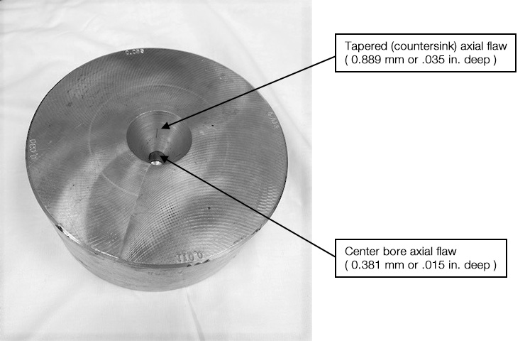
A customer needed a conventional eddy current solution to detect cracks in two areas of a rail axle center: the counter and the center bores. The goal was to create a solution to minimize operator intervention with both equipment and instrument settings.
Forging Axle Shafts Introduces Surface and Internal Defects
The axle shafts are forged and then machined down to meet internal specifications. The forging process can generate surface and internal defects, such as hairline subsurface cracks, inclusions, and pitting. When machined, internal deformities can increase in size and break the surface. These defects can lead to part failures.
Although these cracks tend to be surface breaking, a dedicated eddy current inspection method was needed rather than a subjective visual inspection to detect the axial surface-breaking cracks.
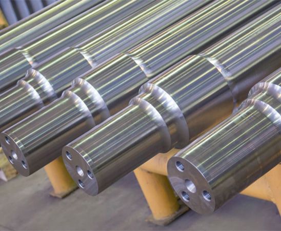
Axles
Eddy Current Equipment Used to Detect Defects in a Rail Axle Center
This inspection used the following equipment:
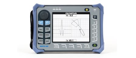
- NORTEC™ 600 eddy current flaw detector
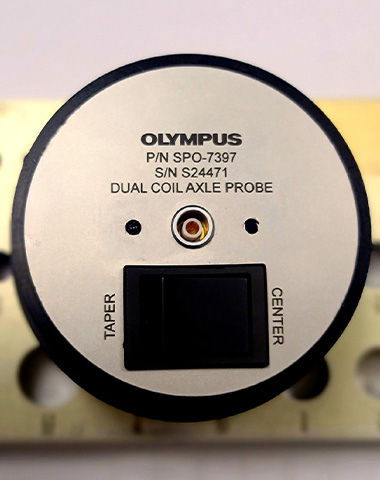
- SPO-7397 custom dual coil axle center probe—Q6100015:
- The probe contains one bridge differential coil to test the length of the tapered section and one small bridge differential coil to test the bottom bore of the axle center
|
|
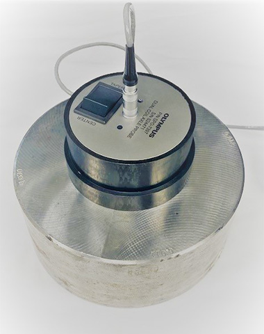
Probe setup to inspect defects in a rail axle center
Procedure to Detect Defects in a Rail Axle Center
The test setup involved placing the probe in the axle center, using the switch to set the area of inspection (taper or center), nulling the coils, and rotating over the electrical discharge machined (EDM) notches provided by the customer.
To change areas of interest, the operator must simply switch the selector to change coils, input the appropriate test settings, and null the instrument.
Both tests can be conducted at 300 kHz with minimal changes in settings. Gain adjustment and angle adjustment can be used to improve results.
Eddy Current Inspection Results
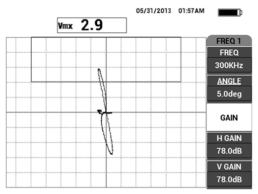
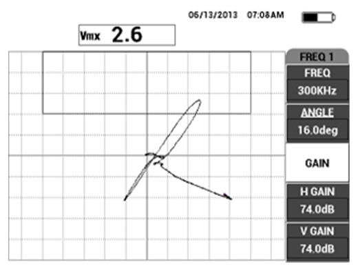
The following images were taken from tests using the SPO-7397 probe on a supplied reference standard in both locations with the NORTEC 600 flaw detector.
Test signal on a notch (0.889 mm or .035 in. deep) in the tapered section of the center |
Test signal on a notch (0.381 mm or .015 in. deep) in the center bore |
Conclusion
Tests conducted on the customer-provided samples with noted flaws were resolved.
As seen in the instrument screenshots, notches on the customer-supplied test/reference standard were detected with a favorable signal-to-noise ratio. The eddy current solution reduces the changeover time between area of inspection setups. This successful application may lead to further probe designs for different axle geometries and can also be implemented into an automated solution.