Application-Specific, Low-Frequency Ultrasonic Solutions for the Inspection of GFRM and CFRM Wind Turbine Blades
Overview of Wind Turbine Blade Bonding Inspection Requirements
Throughout its operating life, a wind blade is subjected to considerable lift forces. To ensure the essential shear strength of the blade assembly, the top and bottom blade shells are bonded together around a set of shear webs. The spar cap, the part of the shell that is bonded to the shear webs, is usually made of thick GFRM (glass fiber-reinforced materials) or CFRM (carbon fiber-reinforced materials) for additional structural solidity. The integrity of the wind blade is highly dependent on the quality of the bonding between the shear webs and spar caps.
To verify the material and bonding integrity, Olympus has developed a set of tools to complete its range of phased array (PA) and ultrasonic testing (UT) inspection solutions. These solutions are fully compatible with OmniScan™ flaw detectors and can also be used with FOCUS PX data acquisition instruments—up to 4 at one time—to achieve a higher throughput.
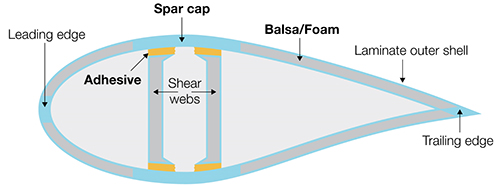
Typical cross section of a wind turbine blade
Issues with Inspecting Spar Cap and Shear Web Bonding Using Ultrasound
As the shear web and the spar cap are bonded together by a layer of adhesive of varying thicknesses, there are two interfaces that must be examined: (1) between the spar cap and the adhesive and (2) between the adhesive and the shear web.
In addition to the structural complexity of wind blades, the acoustically unfriendly nature of the assembly materials can be an inspection hurdle. Wind blade shells are typically fabricated using fiberglass, and the adhesive is made of epoxy. These materials attenuate the ultrasonic beam very rapidly, making ultrasonic examination challenging.
As standard probes and holders are not adapted for wind blade inspections, we have developed improved phased array and UT solutions that feature an optimized probe and holder design.
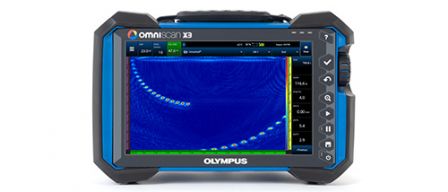
While the OmniScan™ X3 flaw detector is the instrument of choice for manual or semiautomated inspection during manufacturing or in-service inspection, the FOCUS PX acquisition instrument can be used as part of a customized automated inspection system in manufacturing.
Solutions
The Olympus ultrasonic range of solutions is comprised of the following tools:
- 1 MHz RollerFORM™ XL phased array wheel probe
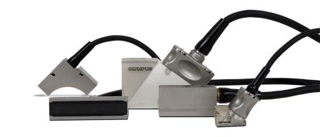
- 0.5 MHz and 1 MHz I5 phased array probes and SI5 holders
- 0.5 MHz M2008 UT probe and SM2008 holders
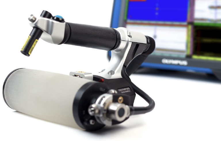
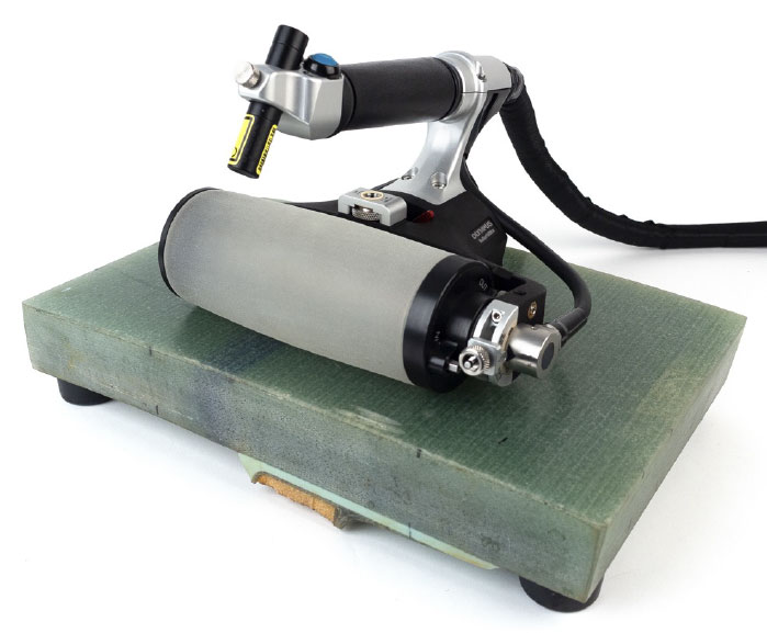
RollerFORM XL phased array wheel probe and scanner
The RollerFORM XL scanner is the latest addition to Olympus’ wind blade inspection solutions. With its 1 MHz low frequency and 13 mm (0.51 in.) aperture, the integrated probe of the RollerFORM XL scanner adds improved penetration in attenuative materials and wider coverage to all the advantages offered by the field-proven standard RollerFORM scanner for the wind energy industry:
- Transportable and easy-to-use package
- Comfortable to operate, reducing fatigue, due to its ergonomic design
- Embedded encoder and laser guide
- Built-in buttons to start the data acquisition and for indexing enable 2D mapping without manipulating the OmniScan instrument.
- Liquid-filled tire made of material with an acoustic impedance similar to water removes the need for coupling system to provide a constant flow of water.
Thanks to its 128 elements with 1 mm (0.04 in.) pitch, which are multiplexed while scanning, the RollerFORM XL scanner offers the largest coverage of our wind blade solutions. This helps to increase your scanning efficiency on large wind blades, requiring fewer passes to cover the area to be inspected.
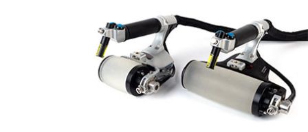
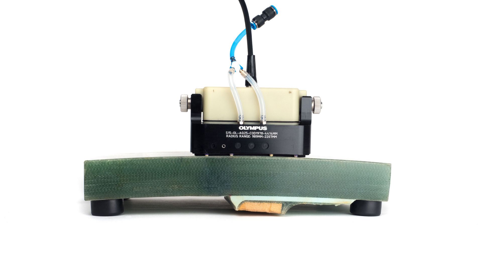
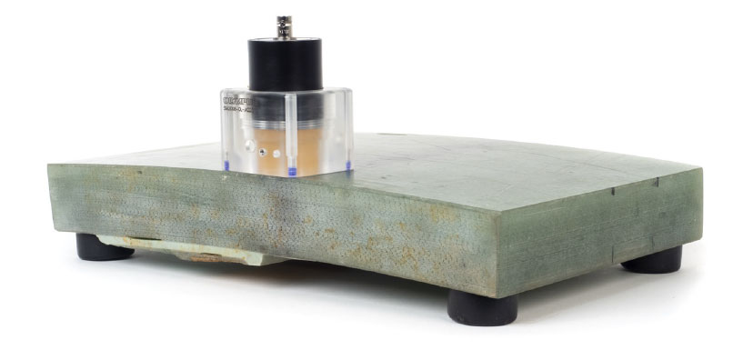
I5 phased array probe and SI5 probe holders
This solution is based on a large aperture low-frequency phased array probe that is mounted on a holder. The probe is available in 0.5 and 1 MHz frequencies and features a 22 mm elevation and 1.5 mm pitch, enabling more energy to travel through thick and attenuative materials. The holder can be fitted with an encoder for manual encoded inspection or mounted on a GLIDER™ scanner for semiautomated 2-axis mapping. Like with the RollerFORM scanner, the ultrasonic beam is multiplexed across the probe’s elements while it is moved along the blade.
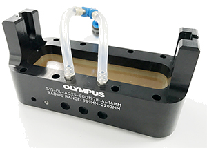
SI5-0L-AQ25-COD1978-4414MM holder model
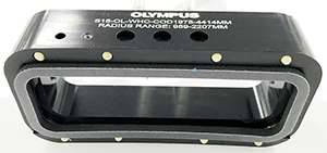
SI5-0L-WHC-COD1978-4414MM holder model
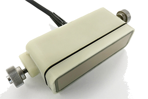
I5 phased array probe
There are two main probe holders: the semicontact design positions the probe surface close to the part surface, whereas the AQ25 design features a 25 mm (1 in.) Aqualene delay line.
The semicontact holder is ideal for inspecting thicker sections of the blade. Its high-energy ultrasonic beam penetrates deeper into the part without any repeated surface echo. The drawback is an increased dead zone close to the surface.
The Aqualene holder improves the resolution near the surface and is therefore more adapted for thinner components (up to 40 mm [1.6 in.] thick).
Both designs come in a flat or contoured variation. While the contoured model is ideal for scanning along the length of the blade, the flat model can be used to scan across the width.
M2008 delay line transducer and SM2008 holders
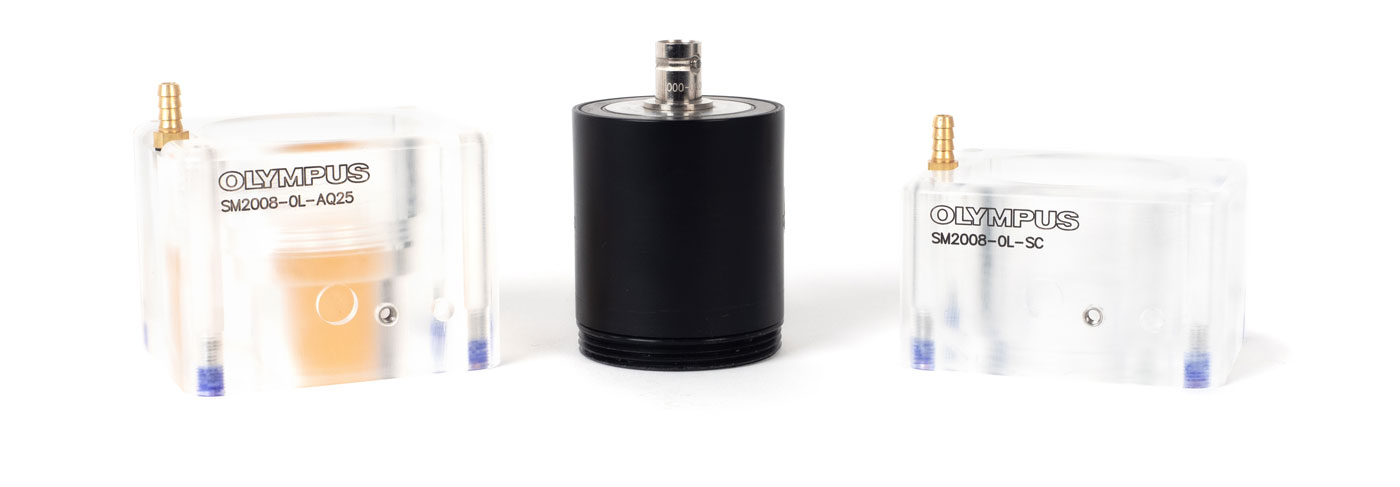
SM2008-0L-AQ25
M2008 0.5 MHz probe
SM2008-0L-SC
This ultrasonic testing (UT) solution represents an affordable option to assess wind blade integrity when coverage and C-scan resolution are less of a concern. This solution can also be used with a Mini-Wheel™ encoder or mounted on the GLIDER scanner for encoded acquisition. However, there are limitations to consider. Mapping a large surface will take more time than with our larger aperture solutions and the probability of detection (POD) for defects is not as high as when using phased array.
Similarly to the SI5 holders, the SM2008-SC holder offers a semicontact inspection for thicker parts, and the SM2008-AQ25 with its 25 mm (1 in.) tall Aqualene delay line offers better near-surface resolution on parts that are up to 40 mm (1.6 in.) thick.
Case Studies Using PA and UT Wind Blade Inspection Solutions
Test 1: Thick Spar Cap Volume Inspection
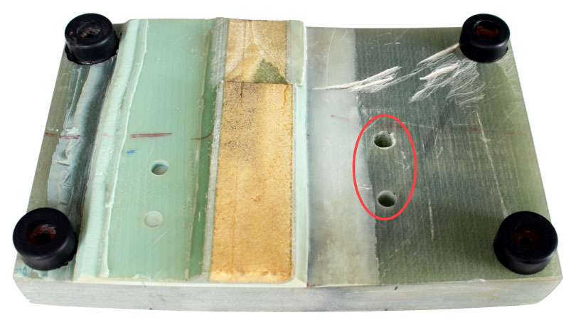
Sample
This test was performed on a sectioned sample of a wind turbine blade featuring two 12.5 mm (0.5 in.) diameter flat-bottom holes (FBH) positioned at 16 mm (0.6 in.) and 32 mm (1.2 in.) deep. These manufactured flaws simulate delamination within the volume of the spar cap.
Setup
For phased array probes, linear 0-degree focal laws were used with a focus at 25 mm (1 in.) in the material. The voltage was set to 115 V and time-corrected gain (TCG) was used to bring the two indications to approximately 80% amplitude. The active aperture length used for each beam was set at approximately 16 mm (0.6 in.), which represents 16 elements with the RollerFORM XL scanner and 12 elements with the I5 probe. The resolution was set to 1 element increments on the I5 for a 1.5 mm (0.06 in.) resolution and to 2 element increments on the RollerFORM XL probe for a 2 mm (0.08 in.) resolution. The voltage on the M2008 transducer was set to 295 V.
Results
RollerFORM XL scanner
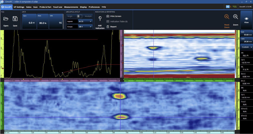
A-scan, S-scan, and amplitude C-scan data acquired with a 1 MHz RollerFORM XL scanner on an OmniScan X3 flaw detector
I5 probe and SI5 holder
Although, the semicontact SI5 holder would have been a more logical choice for this sample, the SI5-AQ25 holder was used to provide more comparable results to the RollerFORM XL scanner.
The following figure shows the results obtained with the SI5-AQ25 holder and the I5 1 MHz probe.
Both indications are easily detected an imaged in the S-scan and amplitude C-scan.
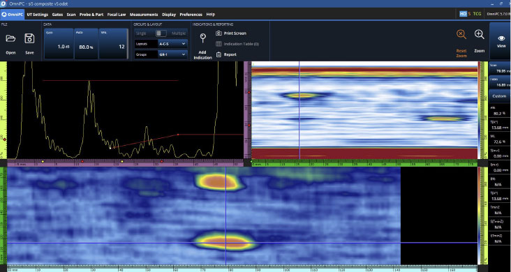
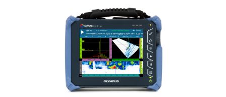
A-scan, S-scan, and amplitude C-scan data acquired with a I5 and SI5-AQ25 holder on an OmniScan X3 flaw detector
M2008 and SM2008 holder
Again, the AQ25 holder was chosen instead of the semicontact holder in order to provide results that can be compared with the RollerFORM XL scanner. The lower 0.5 MHz frequency, although it resulted in a slightly reduced depth resolution, provided an excellent signal-to-noise ratio (SNR) as it was less affected by the mutiple layers in the material.
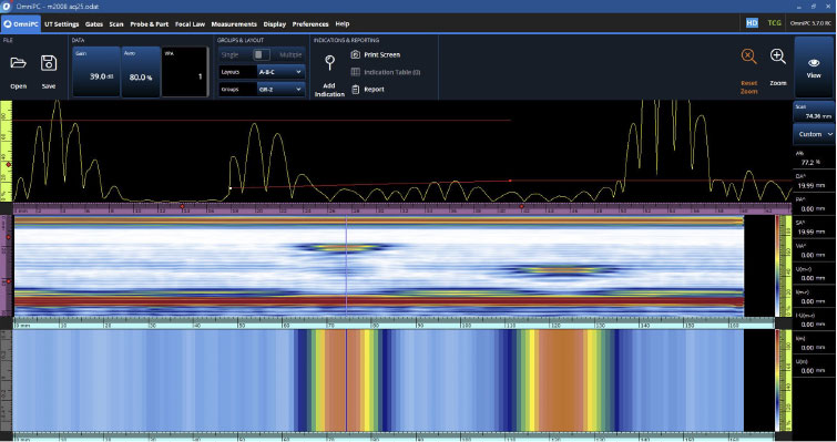
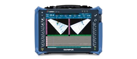
A-scan, B-scan, and amplitude C-scan data acquired with an M2008 UT transducer and SM2008-AQ25 holder on an OmniScan X3 flaw detector
Test 2: Shear Web Bonding Inspection
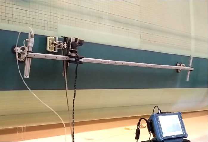
Tests were performed on a wind blade in manufacturing using a customized 2-axis encoded scanner similar to the GLIDER™ scanner. The data was acquired with an OmniScan MX2 flaw detector with a 1 MHz I5 PA probe and semicontact holder.
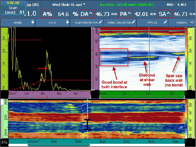
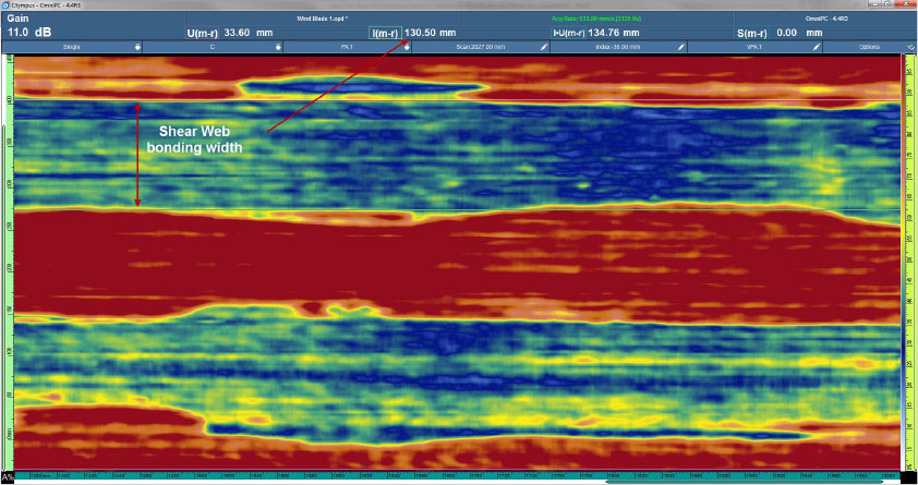
The C-scan is used to have a comprehensive view of the bonding of the two shear webs. The two blue lines represent the bonding interfaces of the shear webs with the spar cap. The ultrasound beam propagates in the shear webs, resulting in a lower amplitude for the return signal. The C scan can also be used to measure the width of the bond using measurement cursors. In this test, the width was approximately 130 mm (5.1 in.). The red areas represent where there is no bonding. There, we observe that the reflected signal from the spar cap back wall is strong.
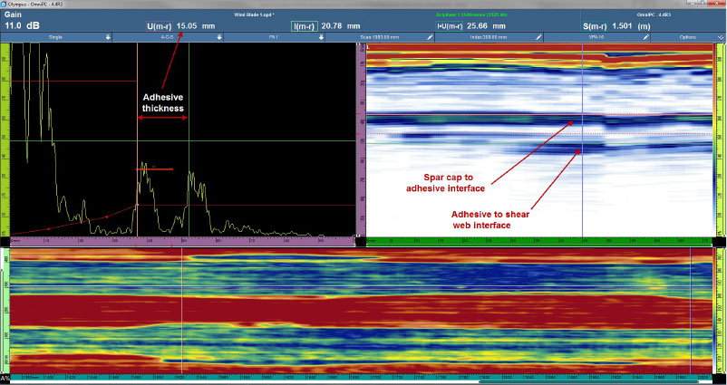
In this application, the adhesive layer was thick enough that both interfaces can be distinguished. Using the measurement cursors in the S-scan and A-scan views, the adhesive was determined to be 15 mm (0.6 in.) thick.
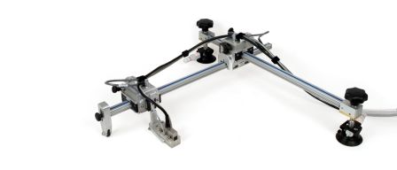
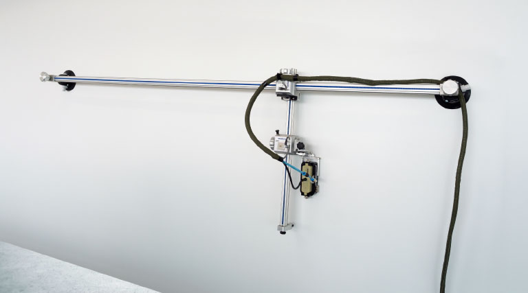
To inspect large areas on wind blades, the use of a 2-axis encoded scanner can be beneficial. The GLIDER scanner is available in a format optimized for the wind blade application. The long axis of the GLIDER scanner, which features a total stoke of 1.8 meters (72 in.), is placed along the length of the wind blade. The length of the second axis is 0.6 meters (24 in.) so it can cover typical shear web configurations.
Test 3: Thin Spar Cap Volume Inspection
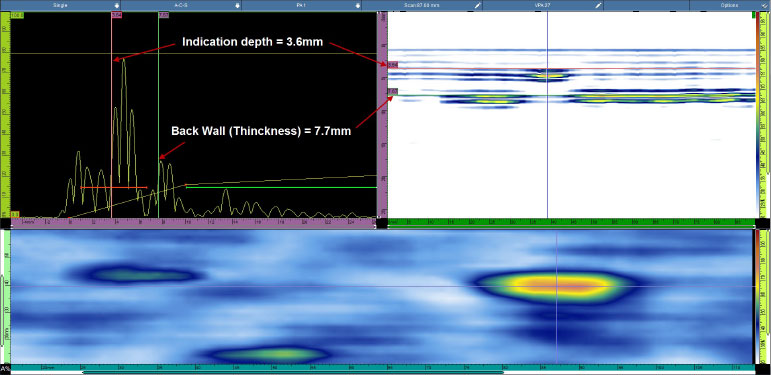
This test was performed on a sample featuring a 12.5 mm (0.5 in.) flat-bottom hole (FBH), simulating lamination in the spar cap. In this case, the spar cap is relatively thin (7.7 mm [0.3 in.]). For that reason, the Aquelene holder (AQ25) was chosen because of its ability to detect defects closer to the surface. The probe is a 1 MHz I5.
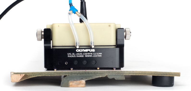
In the image below, we have a clear view of the simulated defect located at 3.6 mm (0.14 in.) under the surface.
Summary of the Advantages of Olympus’ Ultrasonic Wind Blade Inspection Solutions
Olympus has developed a complete phased array (PA) and ultrasonic testing (UT) solution dedicated to the inspection of spar cap and shear web bonding. Although the acoustic attenuation and shape and structure of wind blades makes them a challenge to inspect, the carefully conceived design of this solution resolves those issues while providing high-resolution data and imaging.
Inspecting the structural integrity of wind blades can benefit from all the advantages of phased array ultrasound, enabling higher PODs and less operator-dependent inspections. When deciding which solution fits your needs, consider that the RollerFORM XL scanner is the more convenient option for parts up to 40 mm thick, while the I5 and SI5 solution offers the best performance on thicker and more attenuative materials. The M2008 solution completes the series as an affordable option for inspections on targeted areas of the wind turbine blade.
Download the brochure for more information.