Bolt Inspection Application Overview
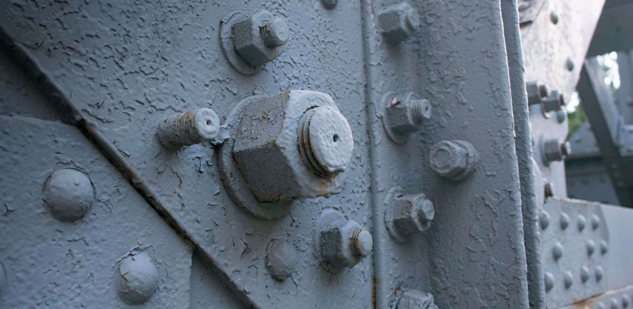
Bolts are prone to various defects, some occurring when being installed, when in service, or during manufacturing. Detecting defects in bolts can help improve machinery and equipment safety and increase these components’ service life.
Solution Using Customized Phased Array Ring-Probe Technology
Phased array ultrasonic testing (PAUT) technology not only enables inspectors to perform high-speed electronic scanning without having to move the probe, but also enables control of the beam characteristics to enhance the inspection performance. A single electronically controlled phased array probe can perform inspections from multiple angles, offering more flexibility in inspecting parts with complex geometric profiles.
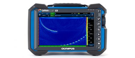
In this app note, we describe several tests carried out using an OmniScan™ X3 flaw detector and a customized ring-array (5D26-12-64) probe to demonstrate this equipment’s efficiency at detecting defects in bolts and similarly shaped parts.
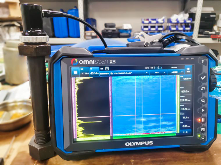
Figure 1. OmniScan X3 flaw detector connected to the ring array probe positioned on a bolt
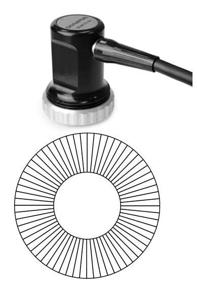
Figure 2. The custom 5D26-12-64 ring-array probe (top) and element distribution schema (bottom)
Specifications of the Customized Ring Array Probe
Outside diameter: 26 mm
Inside diameter: 12 mm
Elements: 64
Total active aperture:
Outer circumference: 81.68 mm
Inner circumference: 37.69 mm
Outer pitch: 1.276 mm
Inner pitch: 0.5889 mm
Elevation: 14 mm
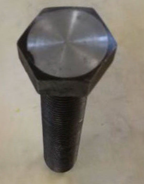
Figure 3. The bolt test block with machined flaws. This test block is a bolt with manufactured defects, namely 1 mm deep grooves located at 20 mm (where the bolt head meets the screw), 80 mm, and 140 mm from the top surface of the bolt head.
Testing Various Firing Sequence Performances Using the Phased Array Ring Probe
Firing Eight Elements of the PA Probe Simultaneously
The following screen captures (Figures 4–6) of the OmniScan X3 flaw detector’s display show the test results on the three defects when 8 elements of the ring-array probe were fired. The linear scanning technique was used, and the probe held in stationary position on the bolt head.
Firing sequence: 1-8, 2-9, 3-10,…57-64
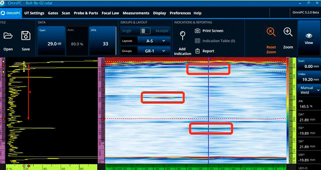
Figure 4. For the defect (groove) located 20 mm from the top surface (where the bolt head meets the screw), its detected depth was 21.89 mm.
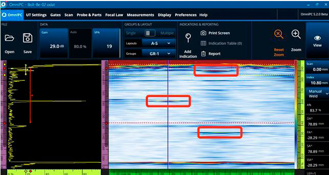
Figure 5. For the defect (groove) located 80 mm from the top surface, its detected depth was 78.89 mm.
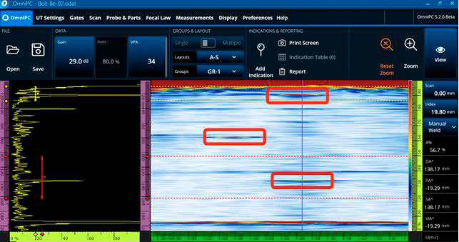
Figure 6. For the defect (groove) located 140 mm from the top surface, its detected depth was 138.17 mm.
Firing Four Elements of the PA Probe Simultaneously
Next, we excited only 4 elements at one time, and all the other conditions remained unchanged. The test results we obtained are shown in Figure 7.
Firing sequence: 1-4, 2-5, 3-6,…61-64
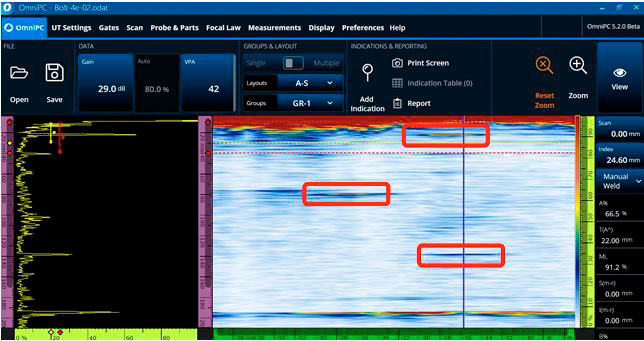
Figure 7. The signals for the shallower defects (grooves) located at 20 mm and 80 mm from the top surface are strong and the indications are clear, whereas the signal for the defect (groove) at 140 mm was weaker.
Firing Two Elements of the PA Probe Simultaneously
When only 2 elements were simultaneously fired, the signal for the defect at 140 mm from the bolt head’s top surface was almost undetectable (see Figure 8).
Firing sequence: 1-2, 2-3, 23-4,…63-64
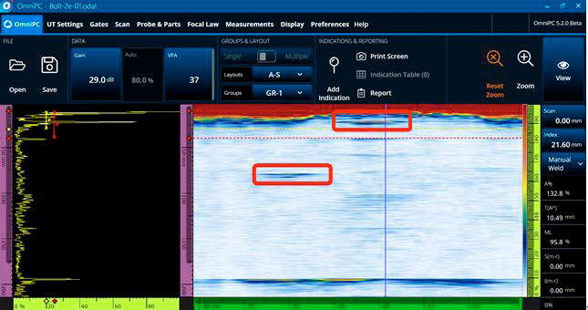
Figure 8: The signal for the defect at 140 mm from the top surface was almost undetectable using two elements.
Firing Sixteen Elements of the PA Probe Simultaneously
Conversely, when 16 elements were excited simultaneously, the signal for the defect at 140 mm from the bolt head’s top surface was displayed more clearly. However, because the 16 elements were in a circular arrangement and thus spanned a large arc, they did not focus effectively and consequently, the signal was stretched and amplified. This is the opposite of what typically happens when a linear array probe is used.
Firing sequence: 1-16, 2-17, 3-18,…49-64
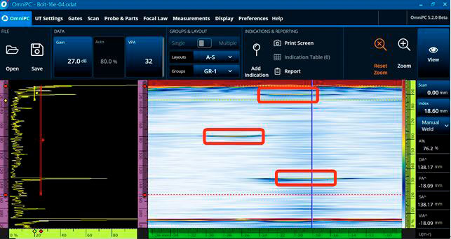
Figure 9: Test results obtained with 16 elements fired simultaneously.
Firing Thirty-Two Elements of the PA Probe Simultaneously
Then we tried firing 32 elements simultaneously, i.e., half of all the elements forming a half circle. Because these 32 elements were arranged in a semicircular arc and were not in a straight line along a horizontal plane, the acoustic beam could not focus, thus resulting in severly distorted signals and making it almost impossible to find the signal for the defect located at 140 mm from the bolt head’s top surface (see Figure 10).
Firing sequence: 1-32, 2-33, 3-34,…33-64
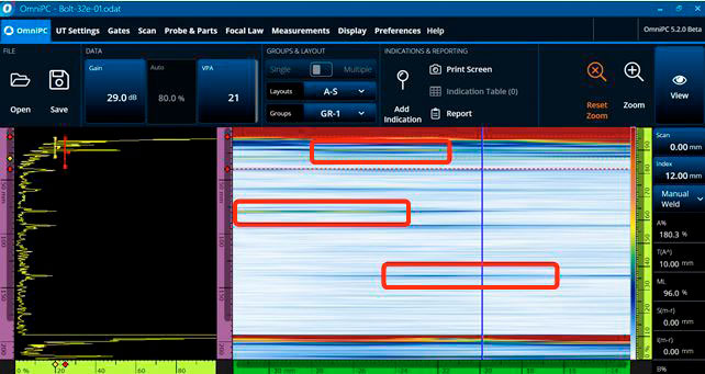
Figure 10: Test results obtained with 32 elements simultaneously excited.
Conclusions Concerning the Results Obtained with Phased Array Ring Probe
Based on the experiment results described above, we concluded the following:
- Relatively better test results can be obtained when 8 elements are simultaneously excited for bolt inspection.
- When fewer than 8 elements are simultaneously excited, the acoustic beam has a weaker penetration, reducing detection performance for deeper defects.
- Conversely, when more than 8 elements are simultaneously excited, because they are not in a straight line, the ability to focus is reduced, resulting in the signal being stretched and amplified.
Comparison Using a Linear Array Probe to Perform Phased Array Sectorial Scanning
This test was conducted to provide a comparison of the ring array probe’s performance with that of a typical linear phased array probe (Figure 11).
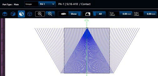
Figure 11. Beam schematic for the linear array probe on the OmniScan X3 flaw detectort
We managed to detect all the defects in the bolt using a linear array probe and a sectorial scanning technique; however, it required additional steps. To detect the defect located at 20 mm from the bolt head’s top surface, it was necessary to use a wedge to increase the beams’ angle of incidence. In addition, the signal for this defect and the signal for the edge of the bolt head’s bottom surface were too close together to distinguish them (Figure 12).
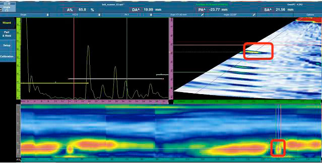
Figure 12. Scan results for the defect located at 20 mm from the bolt head’s top surface.
To detect the defects located at 80 mm and 140 mm from the bolt head’s top surface, we had to use the probe without a wedge to prevent the wedge’s inherent echoes from compromising the inspection results. Figure 13 shows the scan images for the defects located at 80 mm and 140 mm from the bolt head’s top surface. It should be mentioned, however, that after detecting the first defect, the probe had to be rotated to detect the other defect.
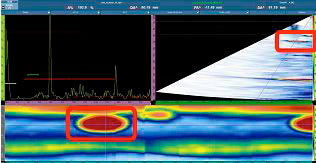
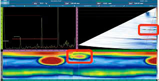
Figure 13. Results for the defects located at 80 mm (left) and 140 mm (right) from the bolt head’s top surface.
Advantages of the Custom PA Ring Array Probe
This experimentation showed that the ring array probe provides the following unique advantages over the linear array probe:
- The ring array probe can detect defects located at all angles without having to rotate it, whereas the linear probe has to be rotated at least 180 to detect defects located at all angles.
- The ring array probe can detect near-surface defects where the bolt head meets the screw without using a wedge, whereas the linear array probe requires a wedge to increase the deflection angle to enable it to detect the near-surface defects in that area.
We also conjecture from the results that the ring array probe will perform well on bolts with a hole in the middle but that the linear array probe’s beams may be impeded by the feature, making it impossible to detect defects. Subsequent experiments will be conducted on real bolts with a center hole to validate the ring array probe’s advantages on these types of bolts.