 |
Application
Confirming the nodularity in ductile iron castings by measuring the velocity of ultrasonic sound.
Background
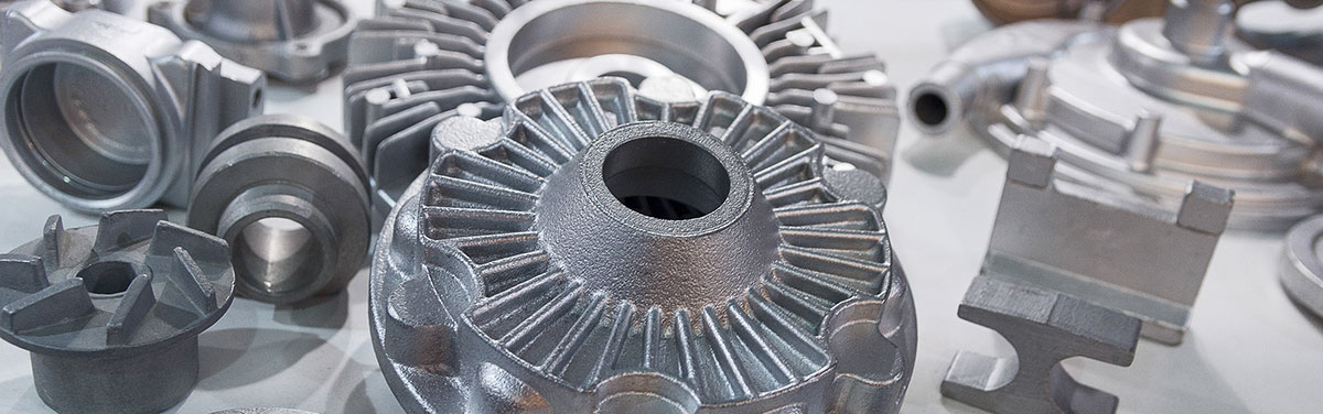
Safety-critical automotive cast parts manufactured from ductile iron must be ultrasonically tested to confirm that they include the correct nodularity. If a safety-critical casting fails, it can result in damage, injury, and even loss of life.
Rounded graphite nodules in the ductile iron matrix offer greater resistance to stress concentration when compared to graphite flakes (as in gray cast iron) and, therefore, inhibit the creation of cracks. Casting manufacturers routinely employ a destructive test method (microstructure analysis) to verify the correct nodularity for sample parts. These tests are conducted in the metallurgical laboratory and tend to represent only a small sample of the total production.
Ultrasonic velocity measurement enables 100% of the manufactured parts to be inspected for nodularity. By correlating the results with destructively tested parts and adjusting the ultrasonic system using castings with known values of nodularity, production parts can be tested and the resulting velocity measurement compared with preset velocity limits to establish accept and reject boundaries. In addition to sound velocity measurement, it is also possible to use pulse-echo ultrasonic probes to verify certain casting features or to detect laminar defects.
The most common method for performing velocity measurement is to use precision test fixtures in an immersion tank. Ultrasonic probes are configured in pitch-catch (or through transmission) mode, the time of flight between the resulting ultrasonic echoes is measured, and the sound velocity is calculated. The sound velocity is measured at a location on the part where sound can be passed through two parallel surfaces that are normal to the probes.
 |
Precisely fixing the parts relative to the ultrasonic probes is critical to the success of this application. Each tested part (including the reference standards that are used for setup) must be held in the same position relative to the probes. The geometry of all tested parts must be the same, and the reference standards must be produced from the same parts that will be tested.
While some customers still manually load and unload the test parts, most high-volume production foundries utilize either mechanical pick-and-place devices or robots to load the parts into the test fixture and then unload the parts after testing. Digital IO signals from the ultrasonic system enable accepted and rejected parts to be automatically sorted. In many cases, rejected parts are retested to help ensure that the rejection was not due to positioning or some other inspection process variable.
 |
Typical procedure
- Each unique casting type (part number) has a specific precision test fixture.
- The immersion probes are integral to the fixture.
- The fixture is installed in the immersion tank.
- Calibration standards are typically chosen from production parts. The sound velocity is measured using a handheld thickness gage, and destructive testing is performed on like parts to validate the nodularity of the selected calibration standards. Part thickness at the tested section is measured accurately.
- Using these calibration standards, the system is calibrated based on the known sound velocity and thickness.
- Velocity and thickness limits are defined in the setup menu.
- After calibration, the system is switched to inspection mode, and production parts are measured.
- The measured values are compared to the limit values.
- The tested parts are dispositioned according to the measurement result — accepted or rejected.
- System recalibration is performed periodically; the frequency is based on the customer’s quality program requirements.
Results
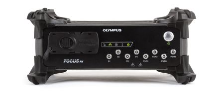
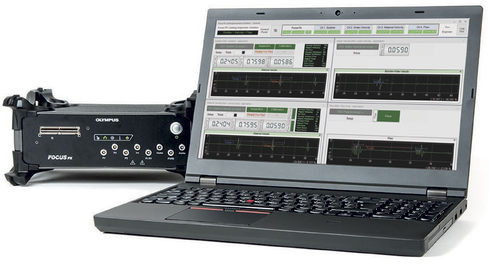
Plant experience with the FOCUS PX™ casting inspection solution has demonstrated that the system is capable of identifying castings with improper nodularity. The development of new software has enabled the integration of many features and functions requested by customers. The client-server architecture of the system enables one channel to be calibrated while the other channels continue to test. The flexibility of the channels used to measure sound velocity, detect casting flaws, and work with bubblers makes it useful in a variety of applications. Both two and four-channel versions are available, and additional channels may be added upon request.
Conclusion
Ultrasonic velocity testing has long been recognized as an effective method to confirm the nodularity of safety-critical cast iron automotive components. As long as the system and the fixtures are well maintained, a reliable result is achieved.
For a more detailed examination of this process, please see Ron Peoples’ article in the April 2017 issue of Quality Magazine.