这篇应用说明概括介绍了铸造工业中的超声无损检测应用,如厚度测量、缺陷探测和球化率的检测。
评估铸件质量
将金属铸造成各种特定形状样件的技艺已经存在了几千年,但只是在近几十年才出现了有助于确保产品完整性的现代超声无损检测工具。在过去,铸造工人会使用一把锤子敲打铸件,通过评估铸件发出的声音而判断铸件的质量。如今,基于微处理器的仪器使用超声波检测技术,可以准确地提供有关铁性和非铁性铸件内部隐藏结构的更多信息。
超声测厚仪可用于测量中空铸件的壁厚。超声探伤仪可用于辨别铸件中的不连续性,如隐藏的多孔性、夹杂物、空隙及裂纹。使用超声测厚仪或超声探伤仪基于声速完成的超声检测还可以量化铸铁材料中的石墨球化率。
超声测厚技术通常用于测量具有复杂形状的中空铸件,如汽车发动机缸体。在汽车发动机缸体的铸造过程中,由于其内核会产生位移,因此可能会造成缸体的一侧太薄,而另一侧太厚的问题。超声测厚仪在无需切割工件的情况下,可以从工件的一侧测量工件的壁厚。
在铸造过程中,金属铸件内部会产生空隙、多孔性、夹杂物和裂纹等缺陷。受过专门训练的操作人员使用一台超声探伤仪和一些适当的探头,就可以使这些缺陷生成超声指示信号,并对信号进行辨别,找到缺陷。
石墨夹杂物的大小与分布情况(球化率)对铸铁的机械强度有很大的影响。在汽车工业以及那些对铸铁部件的安全操作性能要求很高的其他领域中,球化率的检测特别重要。超声技术在确定球化率程度方面提供了一种可替代显微镜横截面观察和拉伸强度测试的无损检测方式,因为球化率与声速相关。
铸件的超声厚度测量
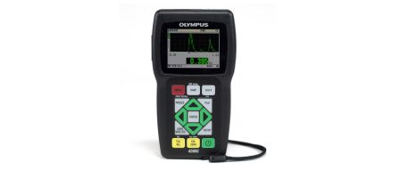
可以使用38DL PLUS超声测厚仪或带有单晶软件的45MG测厚仪进行铸件的壁厚检测。如果被测金属材料的厚度超出了约12.7毫米,则应该使用高穿透软件。 对探头的选择取决于待测厚度的范围和特定铸造金属的声学特性。常用的探头为M106、M1036(以上两个型号探头的频率都是2.25 MHz)、M109和M110(以上两个型号探头的频率都是5 MHz)。在测量超过约50毫米的较厚铸件时,通常建议使用大直径、低频率的探头,如500 KHz的M101型号探头。
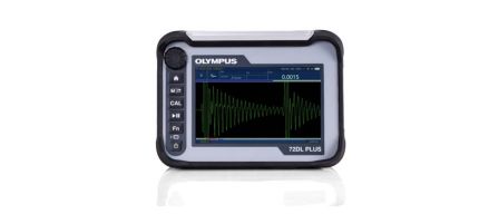
检测铸件壁厚的另一种方案是使用72DL PLUS超声测厚仪。这款高速超声测厚仪的测量速度高达2 kHz,且具有声速模式和穿透检测能力。72DL PLUS超声测厚仪还可被集成到用于监测铸件声速的系统中。
测量铸件壁厚的超声测厚程序
详细的超声测厚仪设置和校准程序在每款仪器的操作手册中有述。此外,耦合剂的选择、表面条件、铸件几何形状、超声测厚仪的校准,以及散射噪声都会影响铸件测量的准确性。
耦合剂:沙模铸件常见的粗糙表面会削弱探头的耦合效果,因此一定要使用高粘度的耦合剂,如凝胶(D型耦合剂)或甘油(B型耦合剂)。
表面条件:如果耦合表面非常粗糙,则特定探头所能测量到的最小厚度将会增加,因为耦合层中会出现声波回响。在仪器计算厚度时,必须要去掉这些回响信号。同样,最大可测厚度也会由于探头与铸件之间的声波耦合效果较差而降低。在大多数情况下,厚度测量可以在铸件原有的表面上进行,但是在具有挑战性的应用中,对表面做一些处理会提高厚度测量的准确性。
几何形状:铸件的内表面和外表面应该基本上处于平行或同轴状态,才可以进行超声厚度测量。如果铸件的内外表面处于极不平行或极不同轴的状态,则声波会偏离探头反射。如果探头接收不到反射信号,屏幕上就不会出现回波。
超声测厚仪的校准:任何超声厚度测量,只有在材料声速与超声测厚仪校准的声速一致的情况下,才可以做到准确无误。声速会在铁性铸件和非铁性铸件中发生变化,因为铸件的硬度和晶粒结构会发生变化,而且在铸铁材料中,石墨球化率也会发生变化。在较大的铸件中,其不同部位会以不同的速度冷却,因此在这种单一铸件的内部,声速也会由于不一致的晶粒结构而发生变化。要获得非常准确的测量结果,超声测厚仪的声速校准一定要使用一种厚度已知,且冶金特性与被测样件相似的参考标准试块完成。
散射噪声:某些铸造金属的粗晶结构会在材料的内部、底面回波的前面产生一些散射噪声。散射噪声会使超声测厚仪软件显示错误的读数,特别是在使用默认的超声测厚仪设置,而不是自行定制的设置时。这种情况可以通过观察波形轻易地诊断出来。内部散射噪声的消除,通常可以通过换用较低频率的探头,或简单地调整仪器的增益和/或空白完成(参见图1和图2中38DL PLUS仪器屏幕上的波形)。
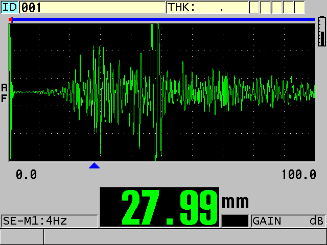
图1. 散射噪声生成错误读数(底面回波出现在视图中部附近)
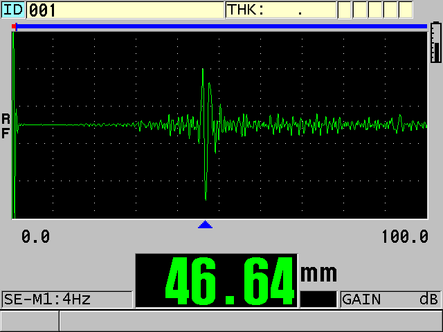
图2. 调整了增益和TDG斜率后得到的正确读数(视图中清晰地显示了底面回波)
用于铸件检测的超声无损缺陷探测
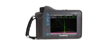
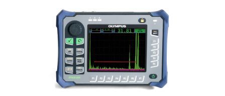
任何奥林巴斯的EPOCH系列超声探伤仪(EPOCH 650和EPOCH 6LT仪器)都可用于铸件检测。双晶探头,如频率在1 MHz到5 MHz之间的DHC系列,常用于检测铸件。这种探头既可以减少来自陷入粗糙铸件表面的耦合剂的反射,又可以优化来自形状不规则的不连续性缺陷的反射。在某些情况下,可以使用角度声束探头探测裂纹。进行自动扫查的专用检测系统,需要使用相同频率范围的水浸探头完成检测。
铸件的超声无损缺陷探测程序
铁性和非铁性铸件的晶粒特性向超声缺陷探测提出了挑战,因为晶粒边界会反射声波,而且随着晶粒大小的增加,晶粒散射噪波的数量也会增加。超声缺陷探测也存在着厚度测量应用所遇到的同样问题:沙模铸件常见的粗糙表面会削弱声耦合效果,并减少回波波幅。在任何特定的检测中,这些因素都会影响最小可探测缺陷的尺寸。因此,精心选择探头,并认真设置仪器,至关重要。
这里推荐使用的检测程序可以优化探头的选择和仪器的设置。检测程序需要借助参考标准试块完成,这个标准试块要体现被测样件的特点,带有已知缺陷,且这些缺陷已经通过有损检测方法、射线成像法或其他非超声技术得到辨别。然后可以将来自这些已知缺陷的指示信号存储起来,并在实际检测过程中,将这些存储的缺陷指示信号与来自被测样件的缺陷指示信号进行比较。 EPOCH 650和EPOCH 6LT超声探伤仪中的带通滤波功能在减少晶粒散射噪声方面非常有用。
图3和图4表明了使用EPOCH 650超声探伤仪和DHC709-RM(5 MHz,12.7 mm直径)双晶探头在40毫米厚的铸铁样件中探测到多孔性缺陷的典型应用。图3中屏幕的右侧显示来自铸件的底面回波,以及沿着基线出现的典型的低水平表面噪声和晶粒噪声。图4显示了一个来自空隙缺陷的指示信号,可以在背景噪声中很容易辨别这个信号。
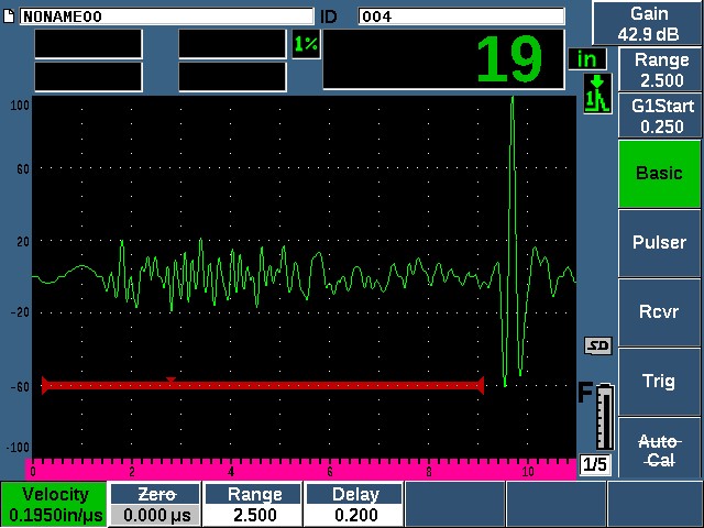
图3. 铸件的合格区域。
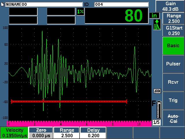
图4. 多孔性缺陷的指示信号。
虽然最常见的铸件缺陷探测应用涉及到对铸件中的空隙、多孔性和夹杂物的探测,但某些用户可能还需要探测裂纹和断裂等缺陷。裂纹检测程序一定要根据铸件特定的几何形状,以及可疑裂纹的位置、大小和方向而开发。而且,裂纹检测需要使用包含已知或人工制成缺陷的适当的参考标准试块。当裂纹面与探头的耦合表面平行时,要使用垂直声束探头。当裂纹与耦合表面垂直或成一定角度时,要使用角度声束探头。请注意由于铸铁和非铁性铸件的声速较低,因此用于钢制样件的楔块的实际折射角度要低一些。只要使用常规钢制楔块检测其他材料制成的样件,就应该通过斯涅尔定律重新计算这些角度。
铸件球化率检测
建议使用奥林巴斯精确超声测厚仪进行球化率检测,因为它们可以根据输入的工件厚度直接显示声速读数。这些仪器包括72DL PLUS、38DL PLUS和带有单晶软件的45MG超声测厚仪。如果金属厚度超出了约12.5毫米,则建议使用38DL PLUS和45MG超声测厚仪的高穿透软件选项。还可以使用任何奥林巴斯的EPOCH系列超声探伤仪,通过声速校准程序获得声速信息。您可以在我们的应用说明测量铸铁的球化率中,阅读到关于球化率检测的更详细信息。