Background:
The friction stir welding (FSW) technique was developed as a method to join materials that are difficult to fusion weld such as aluminum alloys. The quality of the weld obtained is very high and the material structure is uniform. However, the process may generate small, tight defects that are hard to detect.
Friction stir welding is a welding process unlike most others in that there is no liquid state weld pool. As such, the potential defects in the weld are quite different. The defects present in such welds are typically lack of penetration, worm holes, porosity and kissing bonds. This last defect type is formed by a thin oxide layer which prevents fusion of the material despite being in contact. Furthermore, due to the weld process, defects can be orientated in any direction. The weld
“cap” can be quite rough following this inspection technique and it is typically not optimal to use standard Rexolite wedges.
The best method for inspecting friction stir welds is ultrasonic phased array testing using a water-coupled wedge. Because of the weld shape, raster scanning is not practical, but with phased arrays, inspection of the entire weld volume can be done in a single-pass scan. Phased arrays also permit lateral scanning to detect transverse defects. Optimization of the inspection angle maximizes the probability of detection. The increased number of zones covered by phased arrays provides accurate flaw sizing and location. High speed, accuracy, and versatility make phased arrays the choice technique for FSW inspection.
Equipment
The equipment used for the inspection is comprised of:
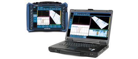
OmniScan SX, MX2 16:64 or 16:128 Phased Array Unit
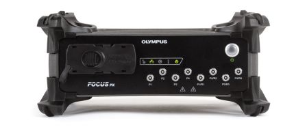
FOCUS PX Acquisition Unit
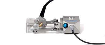
10L64-FSW PA probe
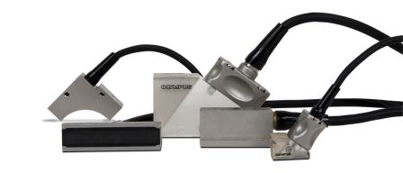
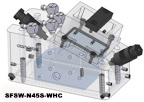
Normal and Lateral water wedges (SFSW-N45S-WHC and SFSW-L45S-WHC)
1 Wing Scanner, VersaMouse or mini-wheel encoder
1 water pump
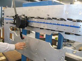
Inspection setup
 | 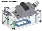 |
Typical irrigated wedges
Typical Procedure
As defects can be orientated in any direction, a single pass inspection is typically not sufficient to detect all defects with an adequate signal-to-noise ratio. As such, the weld would typically be inspected in the 90° direction with the N45S wedge and in the 0° direction with the L45S wedge.
 | 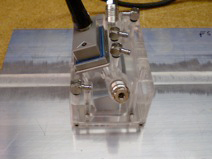 |
Probe positioning for normal (90°) and lateral (0°) scans
The first pass utilizes a linear 45° scan from the normal (90°) direction. A guide can be used to maintain a constant index offset of the probe with respect to the weld along the entire weld line. A position encoder can be attached to the probe to provide a positional reference to scans. In the case of thinner welds a single pass will cover both the weld root and crown. For thicker parts, two passes at different offsets are necessary to obtain full volumetric coverage of the weld
zone.
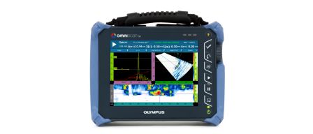
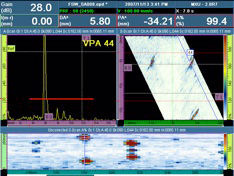
Wedge delay and material velocity are calibrated to obtain relevant skip overlap indications (B0 and T1 in the figure below). Gate A (red) was used to obtain the C-scan. This gate commenced prior to the end of the first skip (B0) and ended after the second skip (T1).
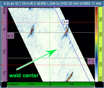
This S-scan image shows notches representing root defects at each extremity of a weld, both appearing in the first leg (reference B0). The probe position allows for entire width of the weld to be inspected simultaneously.
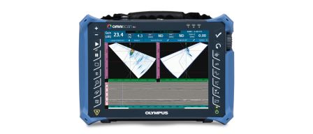
The process is then repeated from the transverse (0°) direction. A similar guide can be used to center the probe along the weld with the probe aligned at 0° to the weld line. A linear scan is acquired by pulling the probe along the weld. C-scans can be generated by placing the gate in between the front wall noise and the significant noise originating from the top surface after one full skip. The corner trap echo from the cracks on the root surface will hit maximum amplitude in the middle of the gate. The corner trap echo from the cracks from the crown will hit a maximum outside the gate in the noisy region. However, these defects can be mapped due to the tip echoes which fall within the gate.
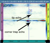
This S-scan shows the corner trap echo and tip crack echo of a transverse notch on the surface of a weld. The red gate (A) begins just after the noise originating from the front wall and ends just before the noise originating from the top surface after one full skip.
Results
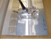
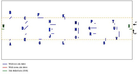
A reference block containing numerous axial and transverse notches as shown below was scanned as described above. As seen in the following C-scan images, the two inspection approaches provided clear indications from all notches that were oriented either parallel or perpendicular to the weld line. Reference notches oriented at 45° to the weld line present more of a challenge. The detection capability in this case depends on the depth and length of the notch. In order to increase the detectability of these defects, additional scans can be performed with the phased array probe skewed at plus and minus 45° from the straight line orientation. This would clearly increase the reflection amplitude from the 45° notches.
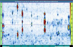
C-scan image from normal incidence scan, showing reflectors aligned along weld axis.
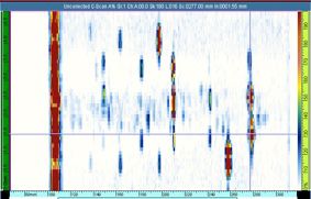
C-scan image from transverse scan, showing reflectors aligned with perpendicular to weld axis.
After the scan has been captured, each indication can be reviewed by selecting a location on the scan via cursors. The captured A-scan at that location can then be displayed as seen below.
Conclusion
Pulse echo inspections of friction stir welds can detect all volumetric-type defects such as cracking, incomplete penetration, and lack of fusion. Transverse defects can be detected using lateral scans. Phased array testing offers the advantages of optimizing inspections by providing focusing and refraction angle selection, as well as providing faster inspections by providing greater coverage in a single pass than a single element angle beam.