Esta nota de aplicação explica como usar transdutores de elemento duplo, comumente conhecidos como dual, para medir a espessura restante do metal em aplicações de corrosão.
Detecção de corrosão usando transdutores de elemento duplo
Praticamente tudo o que é feito com metais estruturais comuns está sujeito à corrosão. Um problema particularmente importante, que muitas indústrias precisam enfrentar, é a medição da espessura da parede remanescente de tubos, canos ou tanques que podem sofrer corrosão na superfície interna. Essa corrosão frequentemente não é detectável por inspeção visual sem cortar ou desmontar o tubo ou tanque. As vigas estruturais de aço, principalmente os suportes das pontes e as estacas de aço, também estão sujeitas à corrosão que reduz a espessura original do metal. Se a corrosão não for detectada no tempo certo, a corrosão irá reduzir as paredes e, provavelmente, causar defeitos estruturais perigosos. As considerações de segurança e econômicas exigem que tubos de metal, tanques ou estruturas que estão sujeitos à corrosão sejam inspecionados regularmente. O teste ultrassônico é um método não destrutivo amplamente aceito para realizar essa inspeção, e o teste ultrassônico de metal corroído geralmente é feito com transdutores de elemento duplo.
Teoria da operação
As superfícies irregulares que são frequentemente encontradas em situações de corrosão dão aos transdutores duplos uma vantagem sobre os transdutores de elemento único. Toda aferição ultrassônica envolve a cronometragem do trajeto de ida e volta de um pulso sonoro em um material de teste. Como o metal sólido tem uma impedância acústica diferente da dos gases, líquidos ou produtos de corrosão, como incrustações ou ferrugem, o pulso sonoro será refletido na superfície distante do metal remanescente. O instrumento de teste é programado com a velocidade do som no material de teste e calcula a espessura da parede a partir desta fórmula simples: Distância = (Velocidade) × (Tempo). A maioria dos medidores projetados para aplicações de corrosão mede o intervalo de tempo do trajeto de ida e volta até o primeiro eco da parede traseira. Muitos instrumentos também podem medir o intervalo entre ecos múltiplos sucessivos. Esta técnica pode ser muito útil em situações que envolvem tinta espessa ou revestimentos semelhantes, no entanto, a medição eco a eco pode ser menos eficaz na detecção de corrosão e medição da espessura mínima real de tubos ou paredes de tanques perfurados. Os transdutores de elemento duplo incorporam elementos de transmissão e recepção separados montados em linhas de atraso que geralmente são cortadas em ângulo com o plano horizontal (o ângulo de teto) de modo que os trajetos do feixe de transmissão e recepção cruzem abaixo da superfície da peça de teste. Este projeto de feixe cruzado de transdutores duplos fornece um efeito de pseudofoco que otimiza a medição da espessura mínima da parede em aplicações de corrosão. Os transdutores duplos são normalmente mais sensíveis do que os transdutores de elemento único aos ecos da base dos poços que representam a espessura mínima restante da parede. Além disso, os transdutores de elemento duplo podem ser usados com mais eficácia em superfícies externas ásperas. O acoplamento preso em bolsões em superfícies ásperas de entrada de som pode produzir ecos de interface longos e vibrantes que interferem na resolução próxima à superfície de transdutores de elemento único. Com um dual, é improvável que o elemento receptor capte esse eco falso. Finalmente, os transdutores duplos podem ser projetados para medições de alta temperatura que danificariam os transdutores de contato de elemento único.
Equipamento:
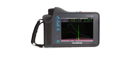
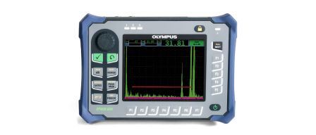
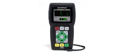
Muitos medidores de espessura ultrassônicos portáteis pequenos são projetados especificamente para aplicações de pesquisa de corrosão. Normalmente, esses medidores são usados com um grupo dedicado de transdutores de elemento duplo, cobrindo várias faixas de espessura e condições de temperatura. Em algumas aplicações críticas, especialmente em temperaturas elevadas, um usuário pode exigir uma exibição de forma de onda ultrassônica para ajudar a verificar se os ecos válidos estão sendo detectados. O medidor de espessura ultrassônico 38DL PLUS™ tem uma tela de forma de onda projetada para esses casos. Para obter detalhes completos, consulte a folha de especificações do instrumento. Outro instrumento projetado para este tipo de teste é o medidor de espessura 45MG. Em aplicações de corrosão, os transdutores duplos também podem ser usados de forma eficaz com detectores de defeitos. Detectores digitais de defeitos, como a série Olympus EPOCH™ (instrumentos EPOCH 650 e EPOCH 6LT), fornecem uma medição de espessura e uma exibição de forma de onda.
Procedimento para fazer medições de espessura de corrosão com transdutores de elemento duplo
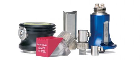
1. Seleção de transdutor
Transdutor | Diâmetro | Freq. | Conector | Espessura mínima aproximada | Raio mínimo aproximado | Limite de temperatura* | ||||
pol. | mm | MHz | pol. | mm | pol. | mm | °F | °C | ||
D790, D790-SM | 0,434 | 11 | 5 | Reto | 0,04 | 1 | 0,75 | 20 | De –5 a 932 | De –20 a 500 |
D791 | 0,434 | 11 | 5 | Ângulo reto | 0,04 | 1 | 0,75 | 20 | De –5 a 932 | De –20 a 500 |
D791-RM | 0,434 | 11 | 5 | Ângulo reto | 0,04 | 1 | 0,75 | 20 | De –5 a 752 | De –20 a 400 |
D792 | 0,283 | 7,2 | 10 | Reto | 0,02 | 0,5 | 0,50 | 12,7 | De –32 a 122 | De –0 a 50 |
D793 | 0,283 | 7,2 | 10 | Ângulo reto | 0,02 | 0,5 | 0,50 | 12,7 | De –32 a 122 | De –0 a 50 |
D7912 | 0,295 | 7,5 | 10 | Reto | 0,02 | 0,5 | 0,50 | 12,7 | De –32 a 122 | De –0 a 50 |
D7913 | 0,295 | 7,5 | 10 | Ângulo reto | 0,02 | 0,5 | 0,50 | 12,7 | De –32 a 122 | De –0 a 50 |
D794 | 0,283 | 7,2 | 5 | Reto | 0,03 | 0,75 | 0,50 | 12,7 | De –32 a 122 | De –0 a 50 |
D797-SM | 0,900 | 22,9 | 2 | Reto | 0,15 | 3,8 | 4,00 | 100 | De –5 a 752 | De –20 a 400 |
D797 | 0,900 | 22,9 | 2 | Ângulo reto | 0,15 | 3,8 | 4,00 | 100 | De –5 a 752 | De –20 a 400 |
D798 | 0,282 | 7,2 | 7,5 | Ângulo reto | 0,02 | 0,71 | 0,50 | 12,7 | De –5 a 300 | De –20 a 150 |
D799 | 0,434 | 11 | 5 | Ângulo reto | 0,04 | 1 | 0,75 | 20 | De –5 a 300 | De –20 a 150 |
D7226 | 0,350 | 8,9 | 7,5 | Ângulo reto | 0,02 | 0,71 | 0,50 | 12,7 | De –5 a 300 | De –20 a 150 |
D7906-SM | 0,434 | 11 | 5 | Reto | 0,04 | 1 | 0,75 | 20 | De –32 a 122 | De –0 a 50 |
D7906-RM | 0,434 | 11 | 5 | Reto | 0,04 | 1 | 0,75 | 20 | De –32 a 122 | De –0 a 50 |
D7908 | 0,283 | 2 | 7,5 | Reto | 0,04 | 1 | 0,50 | 12,7 | De –32 a 122 | De –0 a 50 |
D7910 | 0,500 | 7 | 5 | Ângulo reto | 0,04 | 1 | 1,00 | 25 | De –32 a 122 | De –0 a 50 |
MTD705 | 0,200 | 5,1 | 5 | Ângulo reto | 0,04 | 1 | 0,50 | 12,7 | De –32 a 122 | De –0 a 50 |
2. Condição da superfície
3. Posicionamento/alinhamento do transdutor
4. Medições em altas temperaturas
- Certifique-se de que a temperatura da superfície da peça de teste não excede a temperatura máxima especificada para o transdutor e acoplante que você está usando. Alguns transdutores duplos são projetados apenas para medições de temperatura ambiente.
- Use um acoplante classificado para a temperatura em que você trabalhará. Todos os acopladores de alta temperatura evaporam em alguma temperatura, deixando um resíduo duro que não transmite a energia do som. Aqui estão as temperaturas máximas recomendadas para nossos acoplantes:
Número da peça
Descrição
Volume
Aplicação
B2
Glicerina
0,06 l
De uso geral, mais viscoso e com alta impedância acústica, o que o torna um acoplante ideal para superfícies rugosas. Para utilização em temperatura ambiente.
D12
Tipo de gel
0,35 l
Para superfícies ásperas, superfícies acima da cabeça ou paredes verticais. Para uso em temperatura ambiente.
H-2
Alta temperatura
0,06 l
Faixa de temperatura de 0 °F (-18 °C) a 750 °F (400 °C) em muitas aplicações de ambiente aberto quando usado de acordo com o procedimento recomendado pelo fabricante.*
I-2
Alta temperatura
0,06 l
Faixa de temperatura 700 °F a 1.000 °F (371 °C a 538 °C); para obter mais detalhes, consulte a SDS.*
*As aplicações típicas de defeito e espessura com UT utilizam filmes finos como acoplantes em um ambiente aberto onde uma pequena quantidade de gás composto pode se dissipar rapidamente. No entanto, se um flash de ignição automática de gás de acoplante improvável for motivo de grande preocupação, este acoplante não deve ser usado acima da temperatura de ignição automática fornecida na SDS.
- Faça medições rapidamente e deixe o corpo do transdutor esfriar entre as leituras. Transdutores duplos de alta temperatura têm linhas de atraso feitas de material termicamente tolerante, mas a exposição contínua a temperaturas muito altas, o interior da sonda aquece a um ponto em que as ligações vão falhar, danificando o transdutor. A função de congelamento do instrumento é útil para capturar uma leitura durante os testes que requerem um breve contato de superfície.
- Lembre-se de que a velocidade do som do material e o deslocamento de zero do transdutor mudarão com a temperatura. Para máxima precisão em altas temperaturas, a calibração da velocidade deve ser realizada usando uma seção da barra de teste de espessura conhecida aquecida na temperatura em que as medições devem ser realizadas. Como alternativa, medidores avançados, como o instrumento 38DL PLUS™, fornecem software que pode ser programado para compensar automaticamente a velocidade de variações de temperatura conhecidas. Todos os medidores de corrosão da Olympus possuem uma função zero semiautomática que pode ser usada para ajustar a configuração de zero em altas temperaturas. Consulte o manual de operação do instrumento para obter detalhes. Para outros medidores e detectores de defeitos, consulte seu manual de operação para obter informações sobre como compensar o desvio zero em temperaturas elevadas. Além disso, com frequência, é necessário aumentar o ganho ao medir em temperaturas elevadas. Todos os medidores de corrosão da Olympus têm ajuste de ganho contínuo ou uma função de aumento de ganho que pode ser usada para essa finalidade.