6.4 Common Test Practices
Scan patterns
In any ultrasonic test, the operator must move the transducer so as to cover the entire material volume that must be inspected, and also to cover the range of orientations needed to detect all likely flaws. While scan patterns should always be established with respect to specific test requirements, a common pattern is like this:
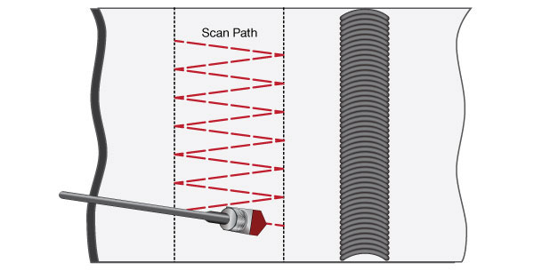
The probe is scanned back and forth between the surface point corresponding to a second leg test of upper part of the weld (left limit in drawing) and the point corresponding to a first leg test of the lower part of the weld (right limit). The wedge is angled slightly in alternate directions, and at each pass it is indexed by approximately one-half its width. This pattern provides full top-to-bottom coverage of the weld while insuring that there are no coverage gaps in the lateral direction, and the angulation helps in detection of inclusions, porosity, and other irregularly shaped reflectors. The test is then repeated from the other side of the weld.
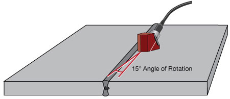
When an indication is observed during this test, procedures may call for further scanning with probe rotation around the reflector and across an outside arc while aimed at the reflector. These motions help identify the type of reflector, as discussed in Section 6.6.
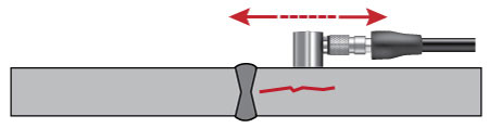
Some procedures also call for a scan along the length of the weld axis, with the wedge aimed slightly inward. The purpose of this scan is to identify transverse cracking in the weld zone, which may not be visible when the beam is directed perpendicular to the weld. Again the test is performed from both sides.
A final test is a straight beam examination of the heat affected zone on both sides of the weld to identify possible laminar cracks. This test typically uses a small diameter contact transducer to identify indications coming ahead of the backwall echo.
Positioning with respect to crown
As noted above, angle beam tests from the side of a weld typically require scanning the probe back and forth between the points where the beam hits the bottom of the weld (first leg) and the top of the weld (second leg). The corresponding points on each side of the weld can be marked with lines on the surface of the parts. Guides or templates can be fabricated to help maintain positioning, especially when performing a single-pass scan of the weld root or crown.
In some cases involving large wedges, relatively thin metal, and large crowns, it may not be possible to position the wedge close enough to the weld to optimize the first leg reflection from the weld root. In such cases a smaller wedge or a wedge designed with a short approach distance should be used. Alternately, testing can be performed in the second and third legs rather than first and second, but that may be less desirable due to attenuation and beam spreading effects.
Contouring
Angle beam inspection of circumferential and axial welds in small diameter pipes and tubes can require contoured wedges for proper coupling. Contouring is generally recommended whenever the diameter becomes small enough that it becomes difficult to hold the wedge normal to the test piece, and/or when curvature significantly limits the area of the wedge in contact with the test piece on a convex radius, or creates a visible gap under the wedge on a concave radius. Typical wedge contours are shown below.
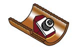 AID (Axial Inside Diameter) | 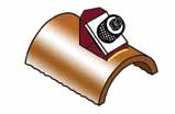 AOD (Axial Outside Diameter) | 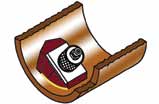 CID (Circumferential Inside Diameter) | 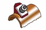 COD (Circumferential Outside Diameter) |