이 어플리케이션 노트는 주조 산업의 초음파 비파괴 시험 적용 분야인 두께 측정, 결함 탐상, 결절형성 시험 등을 총람합니다.
주물의 품질 평가
금속을 특정 형상으로 주조하는 기술은 수천 년 동안 연마되어 왔지만, 제품 무결성 보장에 도움이 되는 최신 초음파 NDT 도구를 사용해온 것은 최근 수십 년 동안에 불과합니다. 과거에는 주조소 작업자가 링의 소리를 평가하기 위해 망치로 주물을 두드려 주물의 품질을 가늠했습니다. 오늘날 초음파를 이용하는 마이크로프로세서 기반 계측기는 철 및 비철 주물의 불명료한 내부 구조에 대한 정보를 더 풍부하고 정확하게 제공할 수 있습니다.
초음파 두께 측정기는 중공 주물의 벽면 치수를 측정하는 데 사용할 수 있습니다. 초음파 결함 탐상기는 숨겨진 기공, 혼입, 간극, 균열과 같은 불연속면을 식별하는 데 사용할 수도 있습니다. 두께 측정기나 결함 탐상기를 사용하는 속도 기반 초음파 검사는 주철의 흑연 결절형성을 정량화하는 데 사용할 수도 있습니다.
초음파 두께 측정은 자동차 엔진 블록처럼 형태가 복잡한 중공 주물을 측정하는 데 주로 사용됩니다. 주조 공정 중 코어 이동으로 인해 한쪽 면은 너무 얇고 다른 면은 너무 두꺼운 부품이 만들어질 수 있습니다. 초음파 두께 측정기는 한쪽에서 벽면 두께를 측정할 수 있으며 측정을 위해 부품을 절단할 필요가 없습니다.
주조 과정에는 금속에 간극, 기공, 혼입, 균열이 발생할 수 있습니다. 이러한 조건은 숙련된 작업자가 적절한 탐촉자를 탑재한 초음파 결함 탐상기로 식별할 수 있는 초음파 표시를 생성합니다.
흑연 혼입(결절형성)의 크기와 분포는 주철의 기계적 강도에 큰 영향을 미칩니다. 결절형성 시험은 주철 부품의 안전한 작동이 매우 중요한자동차 산업과 기타 분야에서 특히 중요합니다. 초음파 기술은 결절형성 정도를 측정하는 현미경 횡단면 검사와 인장 강도 시험에 대한 비파괴적 대안을 제공하며 이는 결절형성과 음속 간 상관관계가 있을 수 있기 때문입니다.
주물의 초음파 두께 측정
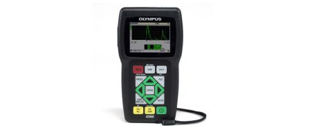
주물의 벽 두께 시험은 Single Element 소프트웨어가 있는38DL PLUS™ 또는 45MG 두께 측정기로 수행할 수 있습니다. 금속 두께가 약 12.7mm(0.5인치)를 초과하는 경우 High Penetration 소프트웨어를 사용해야 합니다. 선택할 탐촉자는 측정할 두께 범위와 특정 주조 금속의 음향 특성에 따라 달라집니다. 일반적으로 사용되는 탐촉자는 M106, M1036(둘 다 2.25MHz), M109, M110(둘 다 5MHz)입니다. 약 50mm(2인치)보다 두꺼운 주물의 경우 500kHz M101처럼 직경이 큰 저주파 탐촉자를 사용하는 것이 좋습니다.
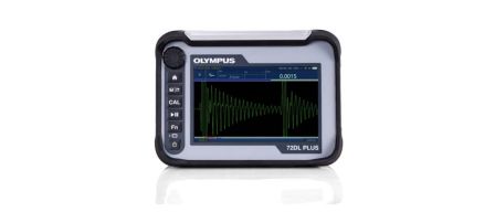
주물의 벽면 두께 시험에는 72DL PLUS™ 측정기도 사용할 수 있습니다. 이 고속 두께 측정기는 속도 모드와 투과탐상법으로 최대 2kHz의 측정 속도를 제공합니다. 72DL PLUS 측정기는 주물의 음속을 모니터링하도록 설계된 시스템에도 통합할 수 있습니다.
주물의 벽면 두께를 측정하는 초음파 측정 절차
자세한 측정기 설정 및 보정 절차는 각 계측기의 사용설명서에서 확인할 수 있습니다. 또한 접촉매질 선택, 표면 상태, 주조 형상, 측정기 보정, 산란 노이즈가 주물의 정확한 측정에 영향을 줄 수 있습니다.
접촉매질: 일반적으로 사형 주물에서 발견되는 거친 표면은 탐촉자 결합을 손상시키므로 항상 젤(접촉매질 D) 또는 글리세린(접촉매질 B)과 같은 고점도 접촉매질을 사용해야 합니다.
표면 상태: 결합 표면이 매우 거칠면 접촉매질 층의 소리 잔향으로 인해 해당 탐촉자로 측정할 수 있는 최소 두께가 증가합니다. 이러한 잔향은 제거해야 합니다. 마찬가지로, 탐촉자와 주물 사이의 음향 결합이 비효율적이라면 측정 가능한 최대 두께가 감소합니다. 대부분의 경우에는 주조된 표면에서 두께 측정이 가능하지만 까다로운 적용 분야의 경우에는 표면 처리가 성능을 향상시킵니다.
형상: 주물의 내부 및 외부 표면은 초음파 측정이 가능하도록 거의 평행하거나 동심이어야 합니다. 벽면이 서로 심하게 어긋나 있으면 음파가 탐촉자로부터 반사되어 화면에 에코가 표시되지 않습니다.
측정기 보정: 모든 초음파 두께 측정은 재료 음속이 측정기 보정과 일치하는 정도까지만 정확합니다. 음속은 경도와 입자 구조의 변화와 흑연 결절형성의 변화로 인해 철 및 비철 주철에서 달라질 수 있습니다. 서로 다른 영역이 다른 속도로 냉각되는 대형 주물에서는 불규칙한 입자 구조로 인해 한 부품 내에서 속도가 다를 수 있습니다. 최적의 측정 정확도를 위해 항상 시험 중인 부품과 야금학적으로 유사하며 두께가 확인된 표준시료에 측정기 속도 보정을 수행하십시오.
산란 노이즈: 일부 주조 금속의 거친 입자 구조는 뒷벽 에코 전에 내부 산란 노이즈를 생성합니다. 산란 노이즈로 인해 두께 측정기 소프트웨어가 잘못된 판독값에 의지할 수 있으며 사용자 지정 설정이 아닌 측정기 기본 설정을 사용할 때 특히 두드러집니다. 이 상태는 파형을 관찰하여 쉽게 진단할 수 있습니다. 내부 산란 노이즈는 주파수가 낮은 탐촉자로 변경하거나 간단히 계측기 게인 및/또는 블랭킹을 조정하여 제거할 수 있습니다(그림 1 및 그림 2의 38DL PLUS 파형 참조).
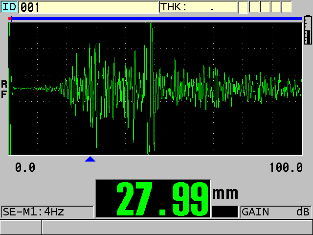
그림 1. 산란 노이즈는 잘못된 판독을 초래합니다(뒷벽 에코가 디스플레이 중앙 근처에서 발생함).
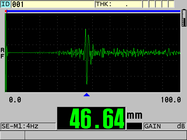
그림 2. 게인 및 TDG 기울기 조정 후의 올바른 판독값(뒷벽 에코가 명확하게 표시됨).
주조 검사를 위한 초음파 결함 탐상
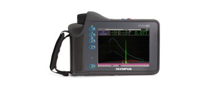
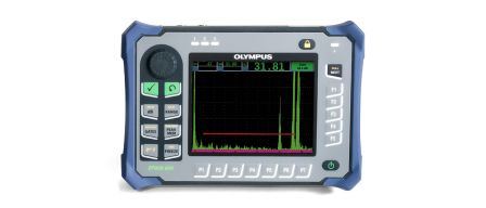
모든 Olympus EPOCH™ 시리즈 결함 탐상기(EPOCH 650 및 EPOCH 6LT 계측기)는 주조 검사에 사용할 수 있습니다. DHC 시리즈와 같은 1MHz~5MHz 주파수의 이중 요소 탐촉자는 거친 주조 표면에 갇힌 접촉매질의 반사를 줄이고 불규칙한 형상의 불연속면에서 반사를 최적화하기 위해 주조를 검사할 때 일반적으로 사용됩니다. 경우에 따라서는 경사각 빔 탐촉자를 균열 탐상에 사용할 수 있습니다. 자동 스캔을 수행하는 특수 시험 시스템은 동일한 주파수 범위에서 침지 탐촉자를 사용합니다.
주물에 대한 초음파 결함 탐상 절차
철 및 비철 주물의 입상 특성은 입계에 의해 생성된 반사로 인해 입경이 증가함에 따라 입계 산란 노이즈의 양이 증가하기 때문에 초음파 결함 탐상에 어려움을 초래합니다. 두께 측정 분야에서와 같이 일반적으로 사형 주물에서 발견되는 거친 표면은 음향 결합을 손상시키고 에코 진폭을 감소시킵니다. 이러한 요인은 모든 시험에서 탐상 가능한 최소 결함 크기를 결정합니다. 이러한 이유로 탐촉자 선택과 계측기 설정에 세심한 주의를 기울여야 합니다.
탐촉자 선택과 설정을 최적화하는 절차가 권장됩니다. 이는 파괴 검사, 방사선 촬영 또는 기타 비초음파 기법으로 확인된 알려진 결함을 포함한 검사할 부품의 샘플에 해당하는 표준시료를 사용하여 수행됩니다. 확인된 결함의 징후를 저장하여 시험 대상의 징후와 비교할 수 있습니다. EPOCH 650 및 EPOCH 6LT 결함 탐상기에서 볼 수 있는 대역 필터링은 입자 산란 노이즈를 줄이는 데 도움이 됩니다.
그림 3과 4는 DHC709-RM(5MHz, 12.7mm[0.5인치] 직경) 이중 소자 탐촉자와 EPOCH 650 결함 탐상기를 사용한 40mm(1.6인치) 주철 기공의 일반적인 시험을 보여줍니다. 그림 3은 기준선을 따라 일반적인 저층 표면 노이즈 및 입자 노이즈와 함께 화면 오른쪽에 있는 주물에서 나오는 뒷벽 에코를 보여줍니다. 그림 4는 배경 잡음과 비교하여 쉽게 식별할 수 있는 간극 결함의 표시를 보여줍니다.
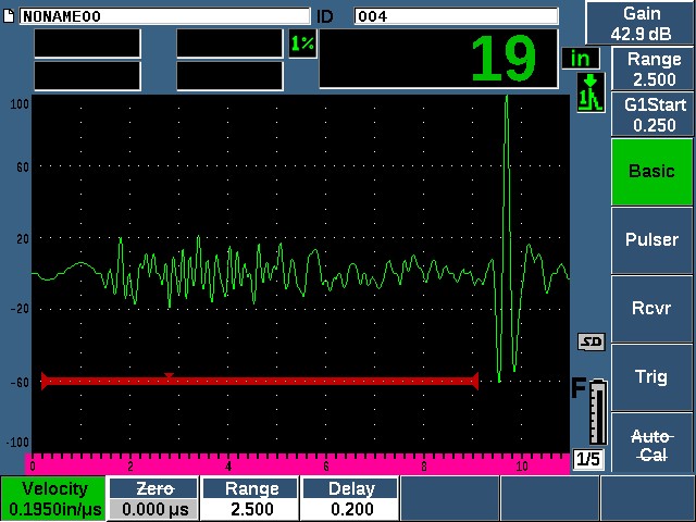
그림 3. 적절한 주조 영역.
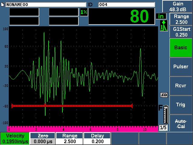
그림 4. 기공 표시.
주물에서 가장 일반적인 결함 탐상 적용 분야는 간극, 기공, 혼입을 포함하지만 일부 사용자는 균열이나 금도 확인해야 합니다. 균열 시험은 항상 주물의 특정 형상뿐만 아니라 의심되는 균열의 위치와 크기, 방향을 고려하여 실시해야 합니다. 또한 균열 시험은 확인되거나 인위적으로 유도된 결함이 포함된 적절한 표준시료를 사용해야 합니다. 직선 빔 탐촉자는 균열면이 탐촉자 결합 표면과 평행일 경우 사용됩니다. 경사각 빔은 균열이 결합 표면에 대하여 수직이거나 기울어져 있을 때 사용됩니다. 주철 주물과 비철 주물의 음속이 낮기 때문에 강철용으로 설계된 웨지의 실제 굴절각은 더 낮습니다. 이 각도는 기존의 강철 웨지를 다른 재료에 사용할 때마다 스넬의 법칙을 사용하여 다시 계산해야 합니다.
주물의 결절형성 시험
Olympus 정밀 두께 측정기는 입력한 부품 두께를 기준으로 음속을 직접 판독할 수 있으므로 결절형성 시험에 권장됩니다. 이러한 계측기로는 Single Element 소프트웨어가 포함된 72DL PLUS, 38DL PLUS 및 45MG 두께 측정기가 있습니다. 금속 두께가 약 12.5mm(0.5인치)를 초과하는 경우 38DL PLUS 및 45MG 측정기용 High Penetration 소프트웨어 옵션을 권장합니다. 또한 모든 Olympus EPOCH 시리즈 결함 탐상기를 사용하여 속도 보정 절차를 수행하고 속도 정보를 얻을 수 있습니다. 당사의 어플리케이션 노트 주철의 결절형성 측정을 읽고 결절형성 시험에 대해 자세히 알아보십시오.