Overview
Most typical TOFD inspections are performed with the send and receive transducers on opposite sides of the weld and scanning movement parallel to the weld axis. The main purpose of this “perpendicular” (defined by beam to weld relationship) scanning is to quickly perform weld inspection with the weld cap or re-enforcement in place. This technique can give location in the scan axis, the indication length, height of indication and flaw characterization information. One of the weaknesses of this technique is the lack of index positioning (or where between the probes) the indication is located. This information is usually obtained with complimentary pulse echo ultrasonics when the weld is left in place. Parallel TOFD scanning, where the scan direction and beam direction are the same is less used, for obvious reasons of not being able to cover the entire length of weld rapidly, more complex movement pattern required of scanner mechanisms, and complexity of the data output of an entire weld inspected. This technique does have advantages when it is possible to be performed.
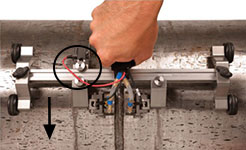
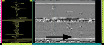
Typical “Perpendicular” Weld Scanning Setup and Data Collected. Data is side view of weld from scan start to scan finish down the weld. Position of encoder and scanning direction are highlighted.
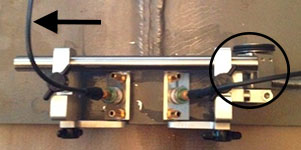
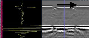
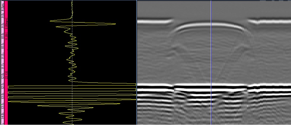
Typical “Parallel” Weld Scanning Setup and Data Collected. Data is side view of weld from scan start to scan finish across the weld. Position of encoder and scanning direction are highlighted.
Benefit of TOFD Parallel Scanning
Although perpendicular TOFD scanning down the weld can give highly accurate depth measurement, generally speaking a parallel scan will give more accurate depth information as well as flaw information, and location in the index position in the weld. With perpendicular scanning, no index position is possible without multiple offset scans being performed or complimentary NDT techniques to position the flaw. In parallel scanning Index position is ascertained by locating the minimum time peak, which corresponds to when the indication is centered between the two probes. For these reasons this technique is often used in critical crack sizing inspections, as well as change monitoring, in other words, monitoring a crack or other defect for growth until it reaches a critical level at which time it is repaired or replaced. For these reasons the technique is often performed on critical components that are costly to shut down for repair, often in the Power Generation industry. More information is often gathered from the flaw as diffraction occurs across the flaw instead of just down the flaw.
Equipment Used
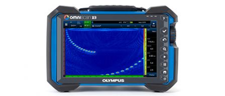
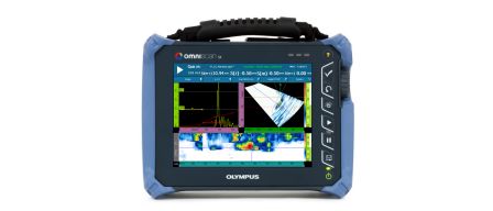
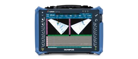
OmniScan SX or MX2
- Instrument options vary, OmniSX-UT (U8779743) minimum recommended platform
TOFD Probes and Wedges
- Centrascan Piezocomposite Transducers- Frequency and Size vary by application
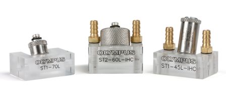
- ST1/ST2 TOFD Wedges-Rexolite and Stainless Steel Options
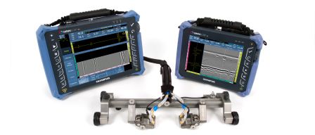
Industrial Scanner and Accessories
- HST-X04 Scanner (U8750007)
- WTR-SPRAYER-4L (U8775153)
Optional Software and Accessories
- OmniPC and NDT Setup Builder (U8775269) or TomoView (U8148031) post analysis software
* Application note created with samples provided by University of Ultrasound