OmniScan MX2
Discontinued Products
Overview
 The result of over 10 years of proven leadership in modular NDT test platforms, the OmniScan MX has been the most successful portable and modular phased array test instrument produced by Olympus to date, with thousands of units in use throughout the world.
Olympus now offers a new PA module with TOFD, a new UT module, as well as new software programs (NDT SetupBuilder and new OmniPC version) that expand the capabilities of the successful OmniScan MX2 platform and improve the workflow efficiency of nondestructive testing inspections.
Learn more about our OmniScan MX2 solutions.
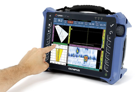
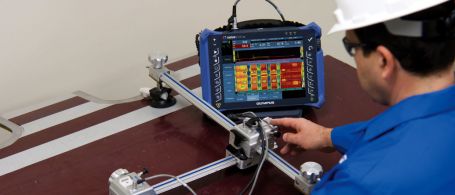
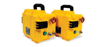
Building on a Solid BasisThis second generation OmniScan MX2 increases testing efficiency, ensuring superior, advanced AUT application performance with faster setups, test cycles, and reporting, in addition to universal compatibility with more than 10 phased array and ultrasound modules. Designed for NDT experts, this high-end, scalable platform delivers true next-generation NDT performance. The OmniScan MX2 offers a high acquisition rate and new powerful software features for efficient manual and automated inspection performance—all in a portable, modular instrument. |
|
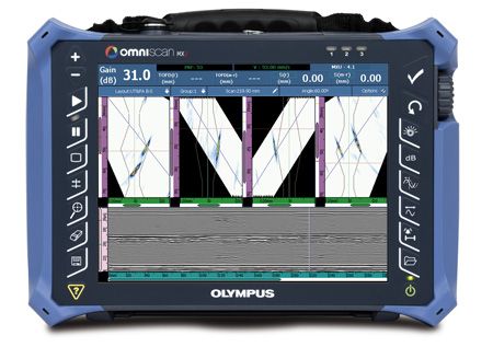
Faster Is Better!Powerstart your day with the OmniScan MX2. The OmniScan MX2 simplifies and speeds up the setup process with its intuitive step-by-step Wizard, so you can start testing quickly. Featuring the industry-standard phased array user interface with faster-than-ever performance, a bigger and brighter 10.4 in. (26.4 cm) screen, new and unique intuitive touch-screen capabilities, and faster data transfer, the MX2 enables you to get to your next inspection quicker. | 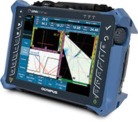 |
More than an Instrument-A Solution Provider
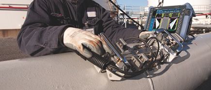
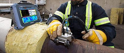
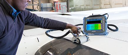
The OmniScan MX2 is an important part of your inspection solution, and can be combined with other critical components to form a complete inspection system. Olympus offers a complete product range that includes phased array probes, scanners, analysis software, and accessories, all of which are integrated and packaged into rapidly deployable, application-specific solutions for a quick return on your investment. In addition, Olympus offers a high-quality global calibration and repair service, backed by a team of phased array application experts to ensure that you get the support you need.
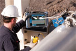 Pressure Vessel Weld Inspection | 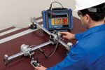 Composite Inspection |  Weld Inspection of Small-Diameter Pipes |  Manual and Semiautomated
|
Modular Instrument
A Platform that Evolves as your Needs Grow
Designed to secure both your current and future phased array investments, the OmniScan MX2 houses more than 10 different Olympus modules. You can be confident that you will get the most out of your investment as specifications will continue to evolve with your needs through constant software updates.
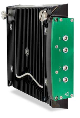
State of the Art PA2 and UT2 Modules
As a world leader in phased array technology, Olympus has released a new line of modules compatible with MX2 instrument.
PA2The new phased array offer-led by the new innovative PA2 modules, features multiple improvements, such as: Best Phased Array and TOFD Signal Quality Ever
More Multi-group Capabilities
General Hardware Improvements
| 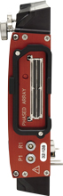 16:64 PA2 16:128 PA2 32:128 PA2 32:128PR PA2 |
UT2The new conventional ultrasound module features the same UT-channel technology as the PA2 modules, but offers twice as many channels. | 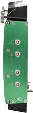 2 ch. UT2 |
Software Features
The new OmniScan software features enhancements for greater functionality in weld and corrosion markets.
In the effort for continuous improvement, the software interface was simplified and the response time optimized in order to provide the best experience possible for customers.
New features include:
- Export C-Scan
- New End-View with group merge
- Interleave
- Analysis attenuation gain
- Scrolling layouts for easy interpretation
- Improved accessibility with more interactive menus
- Optimised main menus and wizards
- Onboard compound scan
- Curved geometry ray-tracing for longitudinal welds
- Phased Array DGS/AVG for all focal laws with S-scan image correction

For applications requiring a multi-probe configuration, the multi-group layouts were improved so that the scanner configuration is reflected in the software interface. The position of the different scans is determined by their distance to the center of the weld, providing an easy-to-understand and appealing layout.
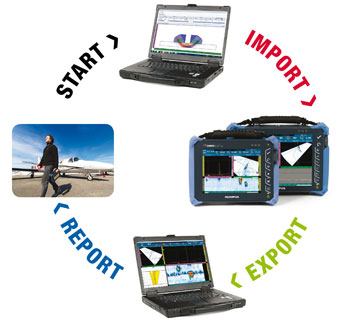
Workflow
The OmniScan Family
DesignNDT SetupBuilder Your needs…
|  |
Acquisition
OmniScan
The OmniScan flaw detectors provide powerful inspection capabilities for manual and automated applications. They can be used with a full range of probes, scanners, and accessories, making Olympus the provider of choice for petrochemical, aerospace, and other industrial markets.
Analysis and Reporting
OmniPC
OmniPC software is the most efficient and affordable option for PC-based OmniScan data analysis, and features the same analysis and reporting tools provided in the OmniScan onboard software.
TomoView
TomoView 2.10 features advanced data processing, analysis and reporting tools that will allow you to get more out of your inspection data.
TomoView high-end features include:
- Volumetric merging for multigroup data visualization.
- C-Scan merging for combined data representation.
- Signal-to-noise (SNR) analysis and optimization tools.
- Advanced offline data generation tools.
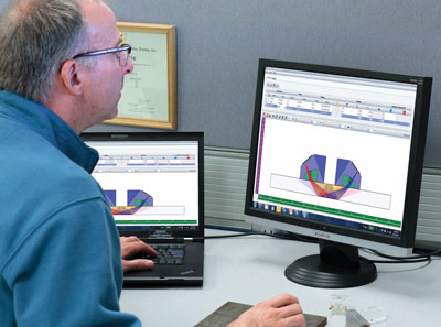
Design with NDT SetupBuilder
NDT SetupBuilder is a new PC-based software allowing to create inspection setup and visualize beam simulations. This software presents multiple features for easy, fast, and comprehensive inspection strategy elaboration that can directly be imported in the OmniScan MX2.
|
|
Setup with OmniScan MX2
The most efficient way to create a setup is to perform the simulation in NDT SetupBuilder, and imported directly, via SD card or USB key, to the OmniScan. Then, only a few basic operations are required in the instrument, such as setting the gate and range, before acquisition can begin. It is also very easy to create a setup right in the OmniScan, thanks to the following features:
|
|
Acquire with OmniScan MX2
Thanks to NDT SetupBuilder and OmniPC campanion software, the OmniScan MX2 can be dedicated exclusively to calibration and acquisition tasks or, if preferred, can perform all the steps of an inspection, right on its large, user-friendly touch screen. |
|

Calibration
To achieve a code-compliant inspection, the Calibration Wizard ensures that every focal law in every group is the direct equivalent of a single-channel conventional flaw detector. The user is guided step-by-step through the required calibrations like: Velocity, Wedge Delay, Sensitivity, TCG, DAC, AWS, and encoder calibrations. Now, TOFD PCS calibration and lateral wave straightening can be performed automatically.
Acquisition
The OmniScan MX2 enables easy configuration of inspection parameters for either manual, one-line, or raster encoded scans. The acquisition is displayed in real time through different views and offers the ability to store data on a hot-swappable SD card or USB 2.0 device.
- Intelligent layouts for configuring up to 8 groups.
- Full-screen mode for better visualization of defects.
- Synchronisation and measurements can be processed using different gate combinations.
Data Analysis with OmniPC
OmniPC is a new software program that benefits form the same user interface and analysis and reporting features as the OmniScan with the added flexibility to be run on a personal computer. With OmniPC, the OmniScan unit can now be used strictly for scanning while analysis is performed simultaneously on a personal computer. This software can also be used in conjunction with extra large screens for increased visibility, and with keyboard shortcuts for faster operations. |
|

Data Analysis with OmniScan MX2
- Data, reference, and measurement cursors for defect sizing.
- Extensive readings database and predefined lists for trigonometry, flaw statistics on axes, volumetric position information, code-based acceptance criteria, corrosion mapping statistics, etc.
- Views are linked for interactive analysis and are automatically updated when performing off-line gate repositioning.
- Optimized preconfigured layouts for quick and simple length, depth, and height sizing of flaws.
Reporting
The OmniScan MX2 and OmniPC can both be used to generate reports with an indication table listing up to eight readings, such as amplitude, position, and size of the defects. The report can also be customized with additional readings and comments specific to each indication, and can be saved as an HTML document. RayTracing tools allow the indication positions to be represented on the weld profile. High-resolution images can be inserted along with all relevant inspection parameters.
Specifications
OmniScan MX2 Mainframe Specifications
| General > Overall dimensions (W x H x D) | 325 mm x 235 mm x 130 mm (12.8 in. x 9.3 in. x 5.1 in.) |
|---|---|
| General > Weight | 3.2 kg (7 lb), no module and one battery |
| Data Storage > Storage devices |
SDHC card*, most standard USB storage devices, or fast Ethernet.
*Lexar® brand memory cards are recommended for optimized results. |
| Data Storage > Data file size | 300 MB |
| I/O Ports > USB ports | 3 |
| I/O Ports > Audio alarm | Yes |
| I/O Ports > Video output | Video out (SVGA) |
| I/O Ports > Ethernet | 10/100 Mbps |
| I/O Lines > Encoder | 2-axis encoder line (quadrature, up, down, or clock/direction) |
| I/O Lines > Digital input | 4 digital TTL inputs, 5 V |
| I/O Lines > Digital output | 4 digital TTL outputs, 5 V, 15 mA |
| I/O Lines > Acquisition on/off switch | Remote acquisition enabled TTL, 5 V |
| I/O Lines > Power output line | 5 V, 500 mA power output line (short-circuit protected) |
| I/O Lines > Alarms | 3 TTL, 5 V, 15 mA |
| I/O Lines > Analog output | 2 analog outputs (12 bits) ±5 V in 10 kΩ |
| I/O Lines > Pace input | 5 V TTL pace input |
| Display > Display size | 26.4 cm (10.4 in.) (diagonal) |
| Display > Resolution | 800 pixels x 600 pixels |
| Display > Brightness | 700 cd/m2 |
| Display > Number of colors | 16 million |
| Display > Type | TFT LCD |
| Power Supply > Battery type | Smart Li-ion battery |
| Power Supply > Number of batteries | 1 or 2 (battery chamber accommodates two hot-swappable batteries) |
| Power Supply > Battery life | Minimum 7 hours with two batteries |
| Environmental Specifications > Operating temperature range |
-10 °C to 45 °C
(14 ºF to 113 ºF) |
| Environmental Specifications > Storage temperature range |
-20 °C to 60 °C (-4 ºF to 140 ºF) with batteries
-20 °C to 70 °C (-4 ºF to 158 ºF) without batteries |
| Environmental Specifications > Relative humidity | Max. 70% RH at 45°C noncondensing |
| Environmental Specifications > Ingress Protection Rating | Designed for IP66 |
| Environmental Specifications > Shockproof rating | Drop-tested according to MIL-STD-810G 516.6 |
| MX2 Module Compatibility > MXU 4.1R8 and later | OMNI-M2-PA32128PR |
| MX2 Module Compatibility > MXU 4.0 and later | OMNI-M2-PA1664 |
| MX2 Module Compatibility > MXU 4.0 and later | OMNI-M2-PA16128 |
| MX2 Module Compatibility > MXU 4.0 and later | OMNI-M2-PA32128 |
| MX2 Module Compatibility > MXU 4.0 and later | OMNI-M2-UT-2CH |
| MX2 Module Compatibility > MXU 3.1 and MXU 4.1R12 and later | OMNI-M-UT-8CH |
Phased Array Module Specifications (Applies to OMNI-M2 modules)
| General > Overall dimensions (W x H x D) | 226 mm x 183 mm x 40 mm (8.9 in. x 7.2 in. x 1.6 in.) |
|---|---|
| General > Weight | 1.6 kg (3.5 lb) |
| General > Connectors |
1 Phased Array connector: Olympus PA connector
2 UT connectors: LEMO 00 |
| General > Number of focal laws | 256 |
| General > Probe recognition | Automatic probe recognition |
| Pulser/Receiver > Aperture | 32 elements* |
| Pulser/Receiver > Number of elements | 128 elements* |
| Pulser | PA Channels | UT Channels |
| Voltage | 40 V, 80 V, and 115 V | 95 V, 175 V, and 340 V |
| Pulse width | Adjustable from 30 ns to 500 ns, resolution of 2.5 ns | Adjustable from 30 ns to 1,000 ns; resolution of 2.5 ns |
| Pulse shape | Negative square pulse | Negative square pulse |
| Output impedance (32:128PR model) |
35 Ω in pulse-echo mode
30 Ω in pitch-catch mode | < 30 Ω |
| Output impedance (all other models) | 25 Ω | < 30 Ω |
| Receiver | PA Channels | UT Channels |
| Gain | 0 dB to 80 dB, maximum input signal 550 mVp-p (full-screen height) | 0 dB to 120 dB maximum input signal 34.5 Vp-p (full-screen height) |
| Input impedance (32:128PR model) |
50 Ω in pulse-echo mode
90 Ω in pitch-catch mode |
60 Ω in pulse-echo mode
50 Ω in pitch-catch mode |
| Input impedance (all other models) | 65 Ω |
60 Ω in pulse-echo mode
50 Ω in pitch-catch mode |
| System bandwidth | 0.5 MHz to 18 MHz (NOTE: The previously stated 0.6 MHz lower limit used a strict −3 dB attenuation for the cutoff frequency.) | 0.25 MHz to 28 MHz (-3 dB) |
| Beamforming > Scan type | Sectorial and linear |
|---|---|
| Beamforming > Group quantity | Up to 8 |
| Data Acquisition > Effective digitizing frequency | Up to 100 MHz |
| Data Acquisition > Maximum pulsing rate | Up to 10 kHz (C-scan) |
| Data Processing | PA Channels | UT Channels |
| Number of data points | Up to 8,192 | |
| Real-time averaging | 2, 4, 8, 16 | 2, 4, 8, 16, 32, 64 |
| Rectifier | RF, full wave, half wave +, half wave – | |
| Filtering | 3 low-pass, 3 band-pass, and 5 high-pass filters. | 3 low-pass, 6 band-pass, and 3 high-pass filters (8 low-pass filters when configured in TOFD) |
| Video filtering | Smoothing (adjusted to probe frequency range) | |
| Data Visualization > A-scan refresh rate | Real time: 60 Hz |
|---|---|
| Data Synchronization > On internal clock | 1 Hz to 10 kHz |
| Data Synchronization > On encoder | On 2 axes: from 1 to 65,536 steps |
| Programmable Time-Corrected Gain (TCG) > Number of points | 32: One TCG curve per focal law |
| Alarms > Number of alarms | 3 |
| Alarms > Conditions | Any logical combination of gates |
| Alarms > Analog outputs | 2 |
* Aperture and number of elements vary with each model. Current shipping models feature 16:64, 16:128, 32:128 configurations.
UT / TOFD
UT2 TOFD Module and MXU Software
The new OmniScan MX2 UT2 module from Olympus represents a powerful, yet affordable solution for TOFD inspection. Several hardware and software improvements make weld inspection using the TOFD technique faster and easier. Leadingclass signal-to-noise ratio provides optimum data quality for TOFD inspection.
Improvements
- TOFD Wizard
- PCS calibration
- Crisper B-scan
- Multi-TOFD layouts
- Lateral Wave straightening
- Higher PRF on TOFD groups
- Higher voltage (up to 340 V) eliminates the need for preamplifiers
These improvements offer a faster and simpler setup, improved acquisition display, and more accurate defect sizing which improves overall productivity.
Multi-TOFD Layouts
The new Multi-TOFD layout can display more than one group at a time. This allows easy positioning and sizing of flaw indications by visual correlation between groups.
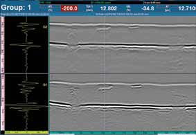
Lateral Wave Straightening
The use of the Lateral Wave straightening tool offers a more coherent display for easier interpretation. Lateral Wave straightening also enables more precise depth evaluation and flaw sizing.
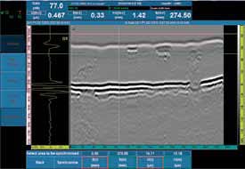 Raw TOFD data | 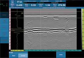 TOFD data after Lateral Wave straightening |
The above mentioned software improvements are also incorporated into the OmniPC software allowing users to analyze data on a PC, while the OmniScan can be redeployed for other data acquisition jobs.
Dedicated Scanners and Accessories
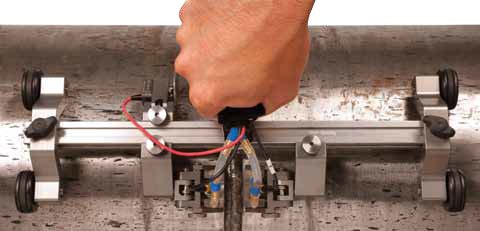
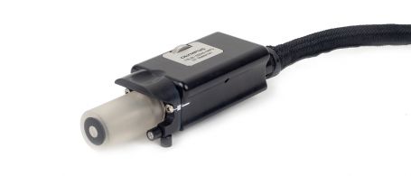
HST-Lite TOFD Scanner
The new HST-Lite scanner is the perfect choice for cost effective, one-channel TOFD inspections when signal quality is important. The combination of magnetic wheels and spring-loaded probe holders offer the stability required to perform high quality, one-line inspections. The scanner can be operated using only one hand, and will attach to ferromagnetic surfaces even when in an upsidedown position.
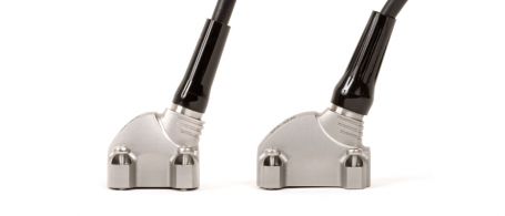
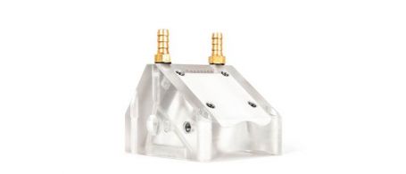
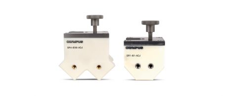
Stainless Steel TOFD Wedges
The HST-Lite, when bought as a kit, comes standard with the new stainless steel TOFD wedges. These wedges are considered a significant upgrade from the common Rexolite wedges, and a better option for most applications. They offer several advantages, including:
| 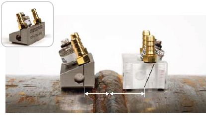 The new stainless steel wedges (on the left) have a shorter approach by 3 mm for better coverage. |
These wedges are compatible with the Olympus high-performance line of TOFD transducers.
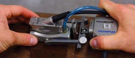
TOFD Inspection of Small Pipes
Designed specifically for use with the wellestablished COBRA scanner, an additional line of TOFD wedges is available for low profile inspections. These wedges can be fitted with 3 mm element diameter ST1 probes to inspect pipes of 1 in. up to 4.5 in. These wedges are available in various longitudinal refracted angles and can be ordered for specific diameters, or from a kit covering the complete diameter range. | 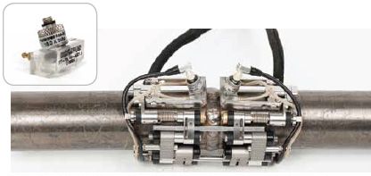 The COBRA small-diameter pipe scanner can perform TOFD inspections with the appropriate wedges, cables, and transducers. |
Click here for ordering information and specifications.
Solutions
Industrial Scanners
Weld Inspection Solutions
Corrosion Inspection Solutions
Composite Inspection Solutions
Scanners
Weld Inspection Scanners
Corrosion Inspection Scanners
Aerospace/Wind Blade Inspection Scanners
Scanner Accessories
Phased Array Probes
RexoFORM
With its unique Rexolite delay line and small footprint, the RexoFORM wedge is optimized for phased array 0° and angle beam inspection in limited-access locations. It offers an economical corrosion mapping solution, conforming to a wide range of pipe diameters without the need for a continuous water supply.
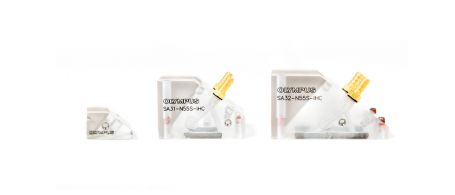
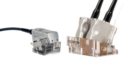
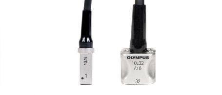
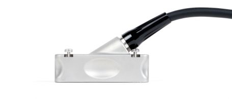
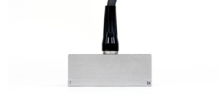
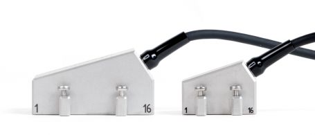
Weld Series Probes
Welding inspection probes offer housings combined with a front or top exit cable to avoid interference with the scanner probe holder. These probes are suitable for manual and automated inspections of welds. Our A31 and A32 weld series phased array probes and wedges simplify and standardize weld inspections, offering an improved signal-to-noise ratio.
Passive-Axis Focusing (PAF) Wedges
This patented focusing wedge series helps compensate for beam divergence in the passive direction for pipe girth weld inspection. The smaller beam width enables the sizing of shorter flaws on the scan axis, helping lower rejection rates, and sharpening the images.
Dual Array Probes for Weld
Dual Array Probe for Corrosion
HTHA Probes
For high-temperature hydrogen attack (HTHA) applications, these optimized Dual Linear Array™ and total focusing method (TFM) probes offer a wider sweeping angle, an expanded focusing range, and an improved signal response when used at high gain.
Manual Contact Probes
EdgeFORM
The EdgeForm phased array solution enables automotive manufacturers to inspect for voids in bonded or glued seams in trunks, hoods, and door panels.
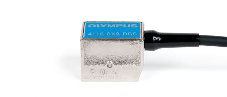
Small-Footprint Probes
Universal Probes
Near-Wall Probes
Deep Penetration Probes

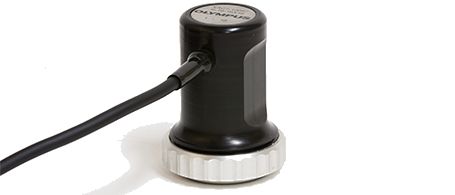
Immersion Probes
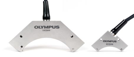
Curved Array Probes
Immersion Corner Wedges for Curved Array Probes
Integrated Wedge and Code Compliant Probes