Wave Front Dynamic Properties with Conventional Transducers
Wave front formation
While a single element transducer may be thought of as a piston source, a single disk or plate pushing forward on the test medium, the wave it generates may be mathematically modeled as the sum of the waves from a very large number of point sources. This derives from Huygens' Principle, first proposed by seventeenth-century Dutch physicist Christiaan Huygens, which states that each point on an advancing wavefront may be thought of as a point source that launches a new spherical wave, and that the resulting unified wave front is the sum of all of these individual spherical waves.
Beam spreading
In principle, the sound wave generated by a transducer will travel in a straight line until it encounters a material boundary. What happens then is discussed below. But if the sound path length is longer than the near field distance, the beam will also increase in diameter, diverging like the beam of a spotlight. The beam spread angle of an unfocused transducer can be calculated as follows:
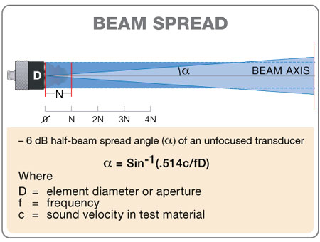
From this equation it can be seen that beam spreading increases with lower frequencies and smaller diameters. Since a large beam spread angle can cause sound energy per unit area to quickly drop with distance, effectively decreasing sensitivity to small reflectors, echo response in some applications involving long sound paths can be improved by using higher frequency and/or larger diameter transducers.
Attenuation
As it travels through a medium, the organized wave front generated by an ultrasonic transducer will begin to break down due to imperfect transmission of energy through the microstructure of any material. Organized mechanical vibrations (sound waves) turn into random mechanical vibrations (heat) until the wave front is no longer detectable. This process is known as sound attenuation.
The mathematical theory of attenuation and scattering is complex. The loss of amplitude due to attenuation across a given sound path will be the sum of absorption effects, which increase linearly with frequency, and scattering effects, which vary through three zones depending on the ratio of the size of grain boundaries or other scatterers to wavelength. In all cases, scattering effects increase with frequency. For a given material at a given temperature, tested at a given frequency, there will
be a specific attenuation coefficient, commonly expressed in Nepers per centimeter (Np/cm). Once this attenuation coefficient is known, losses across a given sound path may be calculated according to the equation
As a practical matter, in ultrasonic NDT applications attenuation coefficients are normally measured rather than calculated. Higher frequencies will be attenuated more rapidly than lower frequencies in any medium, so low test frequencies are usually employed in materials with high attenuation coefficients like low density plastics and rubber.
Reflection and transmission at a perpendicular plane boundary
When a sound wave traveling through a medium encounters a boundary with a dissimilar medium that lies perpendicular to the direction of the wave, a portion of the wave energy will be reflected straight back and a portion will continue straight ahead. The percentage of reflection versus transmission is related to the relative acoustic impedances of the two materials, with acoustic impedance in turn being defined as material density multiplied by speed of sound. The reflection coefficient at a planar boundary, the percentage of sound energy that is reflected back to the source, may be calculated as follows:
From this equation it can be seen that as the acoustic impedances of the two materials become more similar, the reflection coefficient decreases, and as the acoustic impedances become less similar, the reflection coefficient increases. In theory the reflection from the boundary between two materials of the same acoustic impedance is zero, while in the case of materials with very dissimilar acoustic impedances, as in a boundary between steel and air, the reflection coefficient approaches 100%.
Refraction and mode conversion at non-perpendicular boundaries
When a sound wave traveling through a material encounters a boundary with a different material at an angle other than zero degrees, a portion of the wave energy will be reflected forward at an angle equal to the angle of incidence. At the same time, the portion of the wave energy that is transmitted into the second material will be refracted in accordance with Snell's Law, which was independently derived by at least two seventeenth-century mathematicians. Snell's law related the sines of the incident and refracted angle to the wave velocity in each material as diagramed below.
If sound velocity in the second medium is higher than that in the first, then above certain angles this bending will be accompanied by mode conversion, most commonly from a longitudinal wave mode to a shear wave mode. This is the basis of widely used angle beam inspection techniques. As the incident angle in the first (slower) medium such as a wedge or water increases, the angle of the refracted longitudinal wave in the second (faster) material such as metal will increase. As the refracted longitudinal wave angle approaches 90 degrees, a progressively greater portion of the wave energy will be converted to a lower velocity shear wave that will be refracted at the angle predicted by Snell's Law. At incident angles higher than that which would create a 90 degree refracted longitudinal wave, the refracted wave exists entirely in shear mode. A still higher incident angle will result in a situation where the shear wave is theoretically refracted at 90 degrees, at which point a surface wave is generated in the second material. The diagram below shows this effect for a typical angle beam assembly coupled into steel.