Overview of Beam Effects on Linear Array Sectorial Scans
Phased array instruments allow the operator to program a number of parameters that will affect the shape of the sound beam and in turn the graphic resolution of the resulting images.
The scan images below show the effect of increasing the virtual aperture of a phased array probe by pulsing the elements in groups. Using a 64 element probe with a 0.6 mm (0.024 inch) pitch, elements are pulsed in groups of 4, 8, and 16 while imaging side-drilled holes in a reference block. The largest aperture (16 elements) produces an image that is much sharper that that produced by the smaller apertures, and it also gives the highest amplitude response from the target holes. Of course large
apertures can be achieved only with probes that have a large number of elements, which in turn are more expensive and typically require more expensive instrumentation to drive them.
Another variable in setting up a phased array test is the number of programmed focal laws or angular increments in a scan, which effectively controls the number of individual views used to generate an image. A larger number of focal laws will generally produce a more detailed picture, but potentially at the expense of scanning speed and power consumption. Fewer focal laws means that images can update faster and power consumption is reduced, but the resulting images are less sharp.
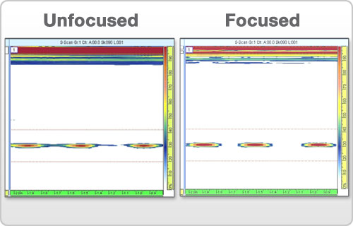
Like aperture and the number of focal laws, electronic beam focusing (as discussed in Section 2.14) can have a significant effect on both the sharpness of an image and the amplitude of the reflection from a target. The scans below show unfocused (left) and focused (right) 5 MHz images of three side drilled holes in a steel reference block.
Perhaps the most fundamental variable affecting graphic resolution is probe selection. Higher frequency will typically offer greater resolution than lower frequencies, while lower frequencies have a penetration advantage in applications involving very long sound paths, or test materials that are highly attenuating or scattering. The scans below show a series of side drilled holes in a steel reference block imaged with a 5 MHz, 64 element probe (left) and a 2 MHz, 16 element probe (right), in both cases using a 16 element aperture. The 5 MHz image is significantly sharper.
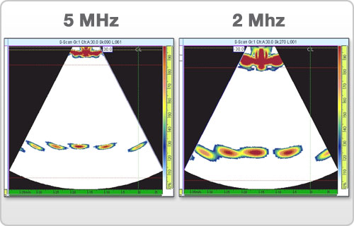
The 5 MHz test does require a higher gain level, since attenuation in any material increases proportionally to frequency. However in most phased array applications system gain is not a limiting factor.
Continue on to Chapter 4
Phased Array Instrumentation >>