Some of the parts that have required inspection lately include landing gears, which are subject to intense stress upon takeoffs and landings. The section that must be inspected is a cylinder possessing three different diameters in the zone of interest. The best way to inspect that zone is to use a phased-array technique with steering capabilities to simultaneously fire 40- to 70-degree shear wave refracted angles in the part.
Material Requirements
Inspection Method |
Olympus Industrial Resources
Application Notes
Back to Resources
Inspection of Landing Gear
 In today's aerospace market, the reliability of airplanes is more than ever a prime concern because airlines companies are trying to make their fleet last longer. To reach this goal safely, these companies must perform more inspections in order to ensure customer safety.
Products Used for This Application
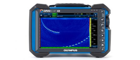
Every flaw detector in the OmniScan™ X3 series is a complete phased array toolbox. Innovative TFM and advanced PA capabilities help you identify flaws with confidence while powerful software tools and simple workflows improve your productivity.
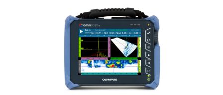
The single group, lightweight OmniScan SX flaw detector features an easy-to-read 8.4-inch (21.3 cm) touch screen and provides cost-effective solutions. The OmniScan SX comes in two models: the SX PA and SX UT. The SX PA is a 16:64PR unit, which, like the UT-only SX UT, is equipped with a conventional UT channel for P/E, P-C, or TOFD inspections.
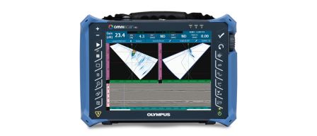
The OmniScan MX2 features a new phased array module (PA2) with a UT channel, and a two-channel conventional ultrasound module (UT2) that can be used for TOFD (Time-of-Flight Diffraction), as well as new software programs that expand the capabilities of the successful OmniScan MX2 platform.
Sorry, this page is not available in your country
Let us know what you're looking for by filling out the form below.