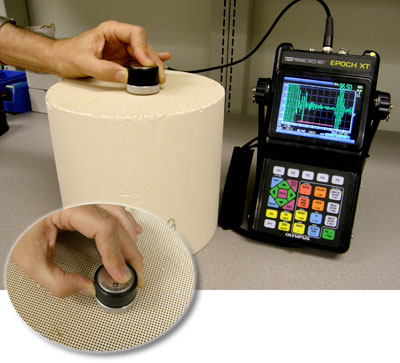
Evident LogoOlympus Logo
Informationsmaterialien
Anwendungsbeispiele
Zurück zur Datenbank

Rissbildungen in Keramik Diesel-Partikelfiltern


Application
Detection of internal cracking in ceramic diesel particulate filters.

Background
The use of ceramic particulate filters is well established as a method for removing environmentally dangerous soot and similar particulates from diesel engine exhaust, especially for diesel engines used in trucks and buses. These filters have the form of large cylinders, approximately 100 mm to 300 mm (4" to 12") in diameter and 150 mm to 350 mm (6 in. to 14 in.) high. They are commonly made of cordierite, silicon carbide, or ceramic in a fine honeycomb pattern. As the hot exhaust is forced through the porous filter under pressure, soot particles collect on the surfaces of the honeycomb channels where they then break down or oxidize due to heat.

These complex ceramic structures can potentially crack during manufacturing, handling, or in service, causing reduced performance or failure that can cause both environmental and engine damage. Ultrasonic testing can quickly and nondestructively detect internal cracking in both new and used ceramic filter elements. The technique usually requires access to only one end of the cylinder.

Equipment
This test can be performed with both conventional flaw detectors and phased array instruments Any of the Epoch-series flaw detectors (Epoch LTC, Epoch XT, or Epoch 1000) can be used with a low frequency contact transducer such as an A601S-RB or V601-RB (500 KHz). A soft polymer membrane on the face of the transducer is used to couple sound energy into the filter without the need for liquid couplants that could be difficult to remove. The Advanced Filter option (available on the Epoch XT and standard on the Epoch 1000) can be helpful for improving signal-to-noise when testing larger filters by improving the instrument's low frequency response. Phased array testing can be performed with the Omniscan or Epoch 1000 and 1.5 MHz probes such as the 1.5L16-A4.

Procedure
Using firm hand pressure, the transducer is coupled to the end of the filter. High frequency sound energy propagating as plate waves travels through the ceramic honeycomb, reflecting off the far end if there are no discontinuities. If there is a crack parallel to the end surface, an echo will be received ahead of the point on the display representing the far end of the filter. If there is a crack that is tilted with respect to the ends, there may be no direct reflection but the echo from the far end will disappear.

In the example below representing a setup with an Epoch XT and an A601S-SB transducer, the left screen image represents a typical echo pattern from an undamaged filter. The echoes at the left side of that waveform represent reverberations of the outgoing sound pulse, and the echoes at the right side represent the reflection from the far end. There should be no significant echoes in the zone in the middle that is marked by the red gate. The right screen image represents an echo pattern from a filter with two cracks parallel to the end, one approximately one-quarter of the way through and one halfway through. The large peak at the right side of that waveform has disappeared because sound energy is no longer reflecting from the far wall, and two new peaks corresponding to the cracks have appeared. The transducer can then be moved to as many points as desired on the face of the filter to check for cracks at other locations.

Typical Backwall Echo from Good Filter

Typical Midwall Echoes from Cracked Filter

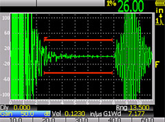
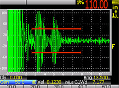
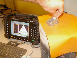
The specific instrument setup for each type of filter should be established through the use of a known good setup standard that is used to optimize the echo from the far end. By identifying the echo pattern from a good filter and looking for changes, a trained operator can quickly and reliably identify echo variations that correspond to internal cracks.

Phased Array Testing

Phased Array can offer cross-sectional imaging of filters from either sectorial or linear scans. This can aid operator visualization of flaws. Automated testing has also been implemented using larger array probes and specialized fixturing.

Olympus IMS

Verwendete Produkte
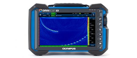
Alle Prüfgeräte der OmniScan X3 Serie sind eine komplette Phased-Array-Toolbox. Innovative TFM-Funktionen und erweiterte PA-Funktionen ermöglichen eine zuverlässige Fehlererkennung. Leistungsstarke Softwarefunktionen und einfache Arbeitsabläufe steigern die Produktivität.
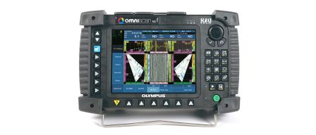
Die OmniScan PA Prüfgeräte dienen der manuellen und automatischen Phased-Array-Prüfung. Sie stellen A-Bilder, B-Bilder, S-Bilder und C-Bilder mit allen Eigenschaften bereit und ermöglicht eine komplexe Datenverarbeitung in Echtzeit. Sie sind mit 16:128 Elementen konfigurierbar, aber auch 16:16M, 16:64M, 32:32 und 32:128
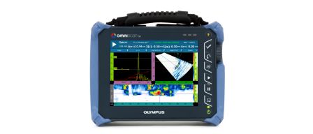
Das OmniScan SX für Einzelgruppen ist leicht, besitzt einen hellen 8,4 Zoll (21,3 cm) großen Touchscreen und stellt eine kostengünstige Lösung dar. Zwei Modelle des OmniScan SX stehen zur Verfügung: das SX PA und das SX UT. Das SX PA (16:64PR) sowie das SX UT verfügen über einen Kanal für konventionellen Ultraschall für IE-, SE- und TOFD-Prüfungen.
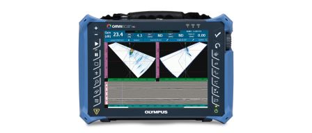
OmniScan MX2 Prüfgeräte verfügen ab jetzt über das neue Phased-Array-Modul PA2 mit einem UT-Kanal und das UT2-Zweikanal-Modul für konventionellen Ultraschall, das auch für TOFD (Laufzeitbeugung) eingesetzt werden kann, sowie über neue Softwareprogramme, die die Leistungsfähigkeit der erfolgreichen OmniScan MX2 Plattform steigern.
Die leistungsstarken EPOCH 650 Prüfgeräte für konventionellen Ultraschall können für zahlreiche Anwendungen eingesetzt werden. Diese intuitiven und robusten Prüfgeräte mit zusätzlichen Funktionen sind die Fortführung der bekannten Prüfgeräte EPOCH 600.
Sorry, this page is not available in your country
Let us know what you're looking for by filling out the form below.
Sorry, this page is not available in your country