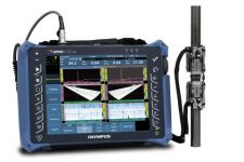
OmniScan MX PA

Přehled
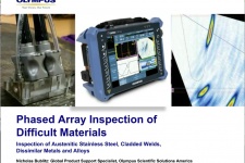
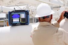
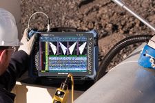
Phased Array Inspection
Phased Array Technology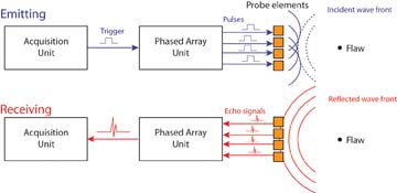
Phased array technology enables the generation of an ultrasonic beam where parameters such as angle, focal distance, and focal point size are controlled through software. Furthermore, this beam can be multiplexed over a large array. These capabilities open a series of new possibilities. For instance, it is possible to quickly vary the angle of the beam to scan a part without moving the probe itself. Phased arrays also allow replacing multiple probes and mechanical components. Inspecting a part
with a variable-angle beam also maximizes detection regardless of the defect orientation, while optimizing signal-to-noise ratio.
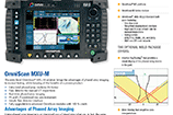
Benefits of Phased Arrays
Phased array technology offers the following benefits:
- Software control of beam angle, focal distance, and spot size
- Multiple-angle inspection with a single, small, electronically-controlled multielement probe
- Greater flexibility for the inspection of complex geometry
- High-speed scans with no moving parts
Phased Array Software
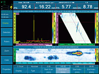
Full-Featured A-Scans, B-Scans, and C-Scans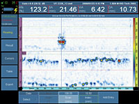
The OmniScan® PA builds upon the OmniScan UT feature set and offers full-featured A-scan, B-scan, and C-scan displays.
Full-Featured Sectorial Scan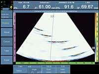
- Real-time volume-corrected representation
- Higher than 20-Hz refresh rate (up to 40 Hz)
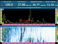
Advanced Real-Time Data Processing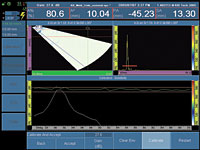
- Real-time data interpolation to improve spatial representation of defects during acquisition of data
- User-selectable high-pass and low-pass filters to enhance A‑scan and imaging quality
- Projection feature allows the operator to view vertically positioned
- A-scan simultaneously with sectorial scan image.
Calibration Procedures and Parameters
All calibration procedures are guided by a step-by-step menu using Next and Back navigation.
Wizards for Groups and Focal Laws
- The Group Wizard allows you to enter all probe, part, and beam parameters, and generate all focal laws in one step instead of generating them with each change.
- The step-by-step approach prevents the user from missing a parameter change.
- Online help provides general information on parameters to be set.
Multiple-Group Option
It is now possible to manage more than one probe with two different configurations: different skews, different scanning types, different inspection areas, and other parameters.
Possible Configurations for Multiple-Group Inspection
A Use one single phased array probe of 64 or more elements and create 2 different groups:
- Linear scan at 45º to cover the upper part using skips on the bottom surface
- Linear scan at 60º to cover the lower part
B Use one single phased array probe of 64 or 128 elements and create 2 different groups:

- Linear scan at 0º at low gain
- Linear scan at 0º at higher gain
C Use one phased array probe of 64 or 128 elements and create 3 different groups:
- Linear scan at 45º to cover the upper part using skips on the bottom surface
- Linear scan at 60º to cover the lower part
- Sectorial scan from 35º to 70º to increase probability of detection
D Use two phased array probes of 16 or 64 elements and create 2 different groups:

- Sectorial scan from 35º to 70º for inspection from left side of the part using skips on the bottom surface
- Sectorial scan from 35º to 70º for inspection from right side of the part using skips on the bottom surface
Specifikace
Phased Array Module Specifications
(Applies to OMNI-M-PA16128)
* Models 16:16, 16:16M, 16:64M, 32:32, and 32:128 also available
| General | |
|
Overall dimensions
(W x H x D) |
244 mm x 182 mm x 57 mm
(9.6 in. x 7.1 in. x 2.1 in.) |
| Weight | 1.2 kg (2.6 lb) |
| Connectors |
1 OmniScan connector for phased-array probes
2 BNC connectors (1 pulser/receiver, 1 receiver for conventional UT) (BNC not available on models 32:32 and 32:128) |
| Number of focal laws | 256 |
| Probe recognition | Automatic probe recognition and setup |
| Pulser/Receiver | |
| Aperture | 16 elements* |
| Number of elements | 128 elements |
| Pulser | |
| Voltage | 80 V per element |
| Pulse width | Adjustable from 30 ns to 500 ns, resolution of 2.5 ns |
| Fall time | Less than 10 ns |
| Pulse shape | Negative square wave |
| Output impedance | Less than 25 Ω |
| Receiver | |
| Gain | 0 dB to 74 dB, maximum input signal 1.32 Vp-p |
| Input impedance | 75 Ω |
| System bandwidth | 0.75 MHz to 18 MHz (-3 dB) |
| Beamforming | |
| Scan type | Azimuthal and linear |
| Scan quantity | Up to 8 |
| Active elements | 16* |
| Elements | 128 |
| Delay range transmission | 0 µs to 10 µs in 2.5-ns increments |
| Delay range reception | 0 µs to 10 µs in 2.5-ns increments |
| Data acquisition | |
| Digitizing frequency | 100 MHz (10 bits) |
| Maximum pulsing rate | Up to 10 kHz (C-scan) |
| Acquisition depth | 29 meters in steel (L-wave), 10 ms with compression. 0.24 meter in steel (L-wave), 81.9 µs without compression |
| Data processing | |
| Number of data points | Up to 8000 |
| Real-time averaging | 2, 4, 8, 16 |
| Rectifier | RF, full wave, halfwave +, halfwave - |
| Filtering | Low-pass (adjusted to probe frequency), digital filtering (bandwidth, frequency range) |
| Video filtering | Smoothing (adjusted to probe frequency range) |
| Data storage | |
| A-scan recording (TOFD) | 6000 A-scans per second (512-point, 8-bit A-scan) |
| C-scan type data recording | I, A, B, up to 10 kHz (amplitude or TOF) |
| Maximum file size |
Limited to available internal flash memory:
180 MB (or 300 MB optional) |
| Data visualization | |
| A-scan refresh rate | Real-time: 60 Hz |
| Volume-corrected S-scan | Up to 40 Hz |
| Data synchronization | |
| On internal clock | 1 Hz to 10 kHz |
| On encoder | On 1 or 2 axes |
| Programmable time-corrected gain (TCG) | |
| Number of points | 16 (1 TCG curve per channel for focal laws) |
| Alarms | |
| Number of alarms | 3 |
| Conditions | Any logical combination of gates |
| Analog outputs | 2 |