Application
Reliable bonds are essential to the integrity of aircraft composite structures throughout their service life. Therefore, NDT methods have been developed to assess bonding quality during maintenance. This application note reviews several methods recently developed to improve the reliability of inspection.
Background
The use of composites in aircraft manufacturing is growing dramatically. Major commercial airframe manufacturers have significantly increased the use of composites in their commercial aircraft. Regional and business jet manufacturers have also increased their use of composite. The same growth is being observed in military aircraft.
Because aircraft structures are subjected to impacts and lightning strikes, reliable and efficient Nondestructive Testing (NDT) methods are needed to quickly assess possible damage. The methods and the necessary instruments have to be easy to use by NDT inspectors all around the world to assure consistency of test results during maintenance checks.
Impacts on aircraft structures can cause different types of damage to composite structures. The damage will vary depending of the nature of the composite part, its composition, and density. On composite laminated structures, defects created by impact are mainly delaminations between different plies of the fuselage and wing skin. But impact can also cause disbonds between the skin and the stiffeners. Such disbond can significantly hurt the integrity of these laminated structures.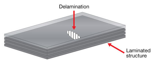
Figure 1: Delamination in a laminated structure
Composite sandwich structures, composed of a sandwich of honeycomb core structures (NOMEX, etc) between laminated carbon skins, present different types of damage. The following defects can be found after an impact:
Type A - delamination between plies of outer CFRP skin, parallel to surface
Type B - disbonding between the outer skin and the honeycomb core
Type C - cracked honeycomb core parallel to the inspection surface
Type D - crushed honeycomb core in parallel area
Type E - disbonding between inner skin and honeycomb core
Type F - fluid ingress in honeycomb core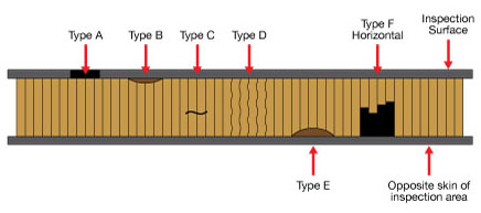
Figure 2: Damages in a composite sandwich structure
Solutions and Equipment
Multi-Mode Acoustic Bond Testing
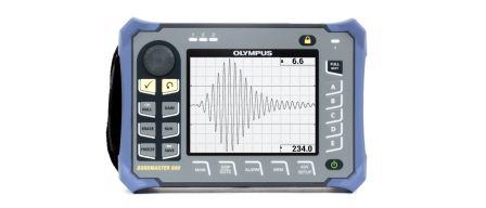
The Olympus Bondmaster 600 is a multimode ultrasonic adhesive bond testing instrument that uses a pitch-catch mode, mechanical impedance analysis (MIA), and resonance testing to inspect composite materials. This instrument has long been used on most existing aircraft, but new methods were developed recently.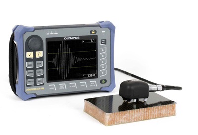
Figure 3: Olympus BondMaster 600
The pitch-catch modes are used to inspect composite materials containing honeycomb structures. The transmitter sends acoustic energy into the part, which is received by the receiver. In a bonded condition, a portion of the acoustic energy is attenuated by the components of the structure. When the probe is placed over a disbonded area, the amount of energy returned to the receiver is greater, resulting in an amplitude change.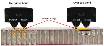
Figure 4: Bond testing pitch-catch mode
An adaptation of this technique was recently developed to allow reliable detection of a disbond (area 25 mm (1 in.) x 25 mm.) located on the far side below 40 mm of honeycomb structure, like a type E defect. A new differential high voltage probe was specifically designed for a difficult and time-consuming inspection of an airplane. This remarkable result is now referenced in commercial airline service bulletins.
Conventional Ultrasonic Testing
Ultrasound is the most widely used technique for inspecting composite structures. There are a large variety of appropriate ultrasonic instruments available. Typically, ultrasound travels very well in composite laminated structures and it can detect anomalies quite easily. Unfortunately, in sandwich structures the ultrasound is extremely attenuated due to the inhomogeneity and low density of the core structure. Therefore, the use of ultrasound for sandwich structures requires more specialized features in instruments.
In a manufacturing environment, large sandwich panels are inspected with through transmission methods in which a relatively high amplitude ultrasound beam travels through the part and a receiving transducer located on the other side measures attenuation of the signal. Results are typically presented as C-scan images. That technique is widely used and is very reliable. But it is impossible to use this technique in a maintenance environment as the required access from both sides of the aircraft structure is impossible.
Nevertheless, ultrasound allows detection of inner and outer skin disbonds, presence of fluids, and crushed cores. Low-frequency transducers and tracking of the backwall signal is necessary and must be used in a very intelligent way. Delamination of the outer skin and disbonds between outer skin and the core are characterised by a total attenuation of the backwall signal.
A technique was recently developed to detect disbonds between the inner skin and the core. The technique uses a broad bandwidth 1 MHz probe when excited by a powerful square wave pulse creates resonance in the structure underneath the probe. The instrument's receiver filter is tuned to the thickness of the structure and to work at the corresponding half-wavelength. Presence of a disbond will reduce the stiffness of the structure causing a resonance shift to longer wavelength, and therefore the resonance frequency will diminish. A 25 mm (1 in.) x 25 mm disbond on the inner structure will cause a backwall signal attenuation of 6 to 12 db due to that phenomenon.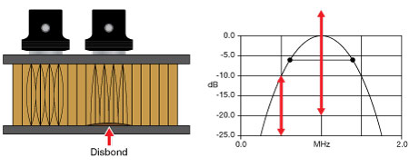
Figure 5: Ultrasonic resonance technique principle
The EPOCH 650 ultrasonic flaw detector with its high voltage pulse, the quality of its square pulse and selectable narrowband filters is the instrument of choice for this technique.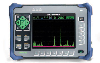
Figure 6: Olympus EPOCH 650
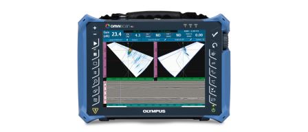
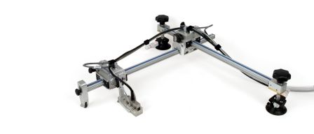
Phased Array Ultrasonic Testing
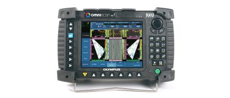
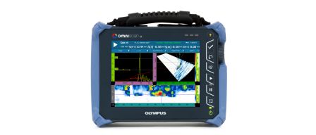
New technologies like ultrasonic phased array also have recent developments. Portable and easy-to-use units are now available on the market. The OmniScan PA is already referenced in maintenance manuals of aircraft manufacturers for various applications, including impact damage detection in composite laminated structures
For such structures, the linear scan capability is used. The instrument performs a zero degree linear inspection covering a large area in one pass. Combined with the use of a portable scanner like the Glider, the system displays results in a C-scan image which give an intuitive mapping of the structures inspected. The combined use of image and scanner increase the reliability and the speed of the inspection.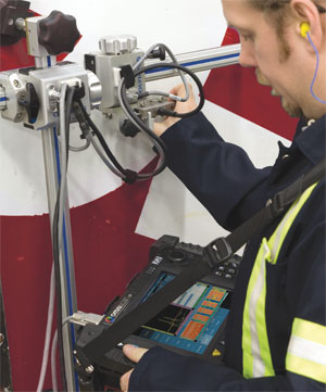
Figure 7: Olympus OmniScan PA and GLIDER for composite inspection
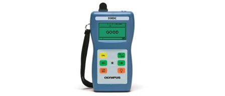
Hand-held Ramp Damage Checker
While a lot of effort has been put into creating new methods and instrument for NDT technicians, the increasing use of aircraft with composite structure has created the need to quickly check for impact damage at the airport during plane turnaround. As NDT technician are not available in all airports of the world, instruments have been designed to be used by non-technicians to detect possible delamination due to impact.
The 35RDC is a simple, go/no-go ultrasonic instrument, created for the inspection of the new aircraft and other composite structures. It was designed to be used by non- NDT-trained personnel to detect subsurface impact damage on solid laminate structures (not honeycomb structures). The concept was developed and then patented by a commercial airline and is based on the well-establish pulse/echo technique. The 35RDC is now referenced in the B787 Structural Repair Data.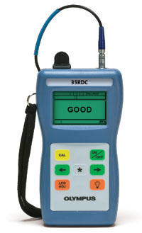
Figure 8: Olympus 35RDC (Ramp Damage Checker)